Using signal strength to identify tire position

a technology of signal strength and tire position, which is applied in the direction of alarms, instruments, transportation and packaging, etc., can solve the problems of not being able to use with a tire pressure monitoring system having only one antenna, and receiving signals with a higher signal strength

Inactive Publication Date: 2002-12-03
VISTEON GLOBAL TECH INC
View PDF35 Cites 172 Cited by
  • Summary
  • Abstract
  • Description
  • Claims
  • Application Information

AI Technical Summary

Problems solved by technology

One challenge in tire pressure monitoring is identifying the location of the tires on the vehicle (e.g., left front, left rear, right rear, etc.).
One drawback of this system is that some signals may be received with a higher signal strength at a reception antenna which is not closest to the position of the transmitting wheel, due to multipath, interference caused by spinning tires and surrounding objects, and other disturbances.
This can lead to inaccurate results, which is disadvantageous in a system where it is very important to avoid providing misleading tire pressure data to the operator.
Furthermore, this system requires multiple reception antennas, and, therefore, cannot be used with a tire pressure monitoring system having only one antenna.

Method used


Image

  • Using signal strength to identify tire position
  • Using signal strength to identify tire position
  • Using signal strength to identify tire position

Examples


Embodiment Construction

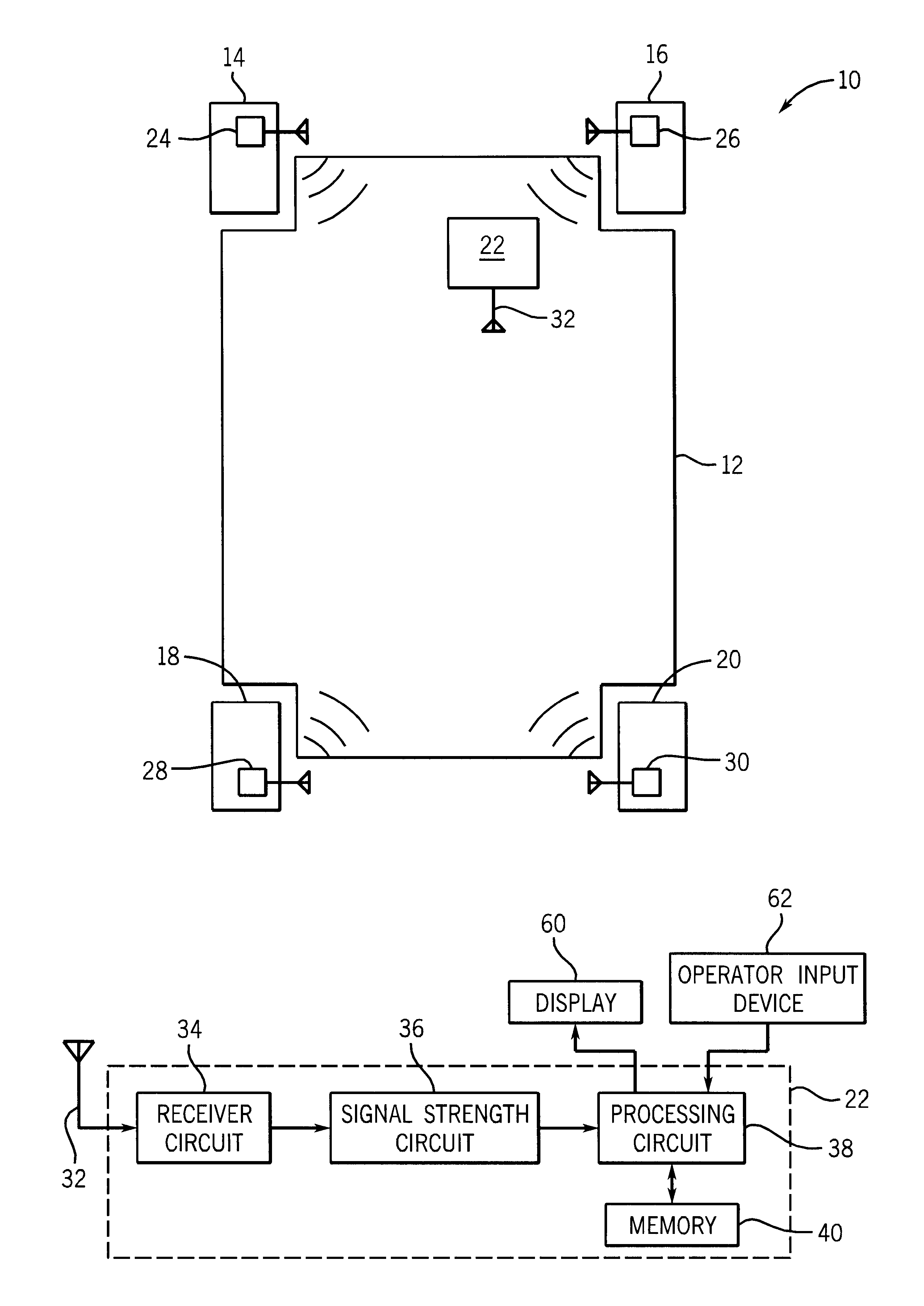
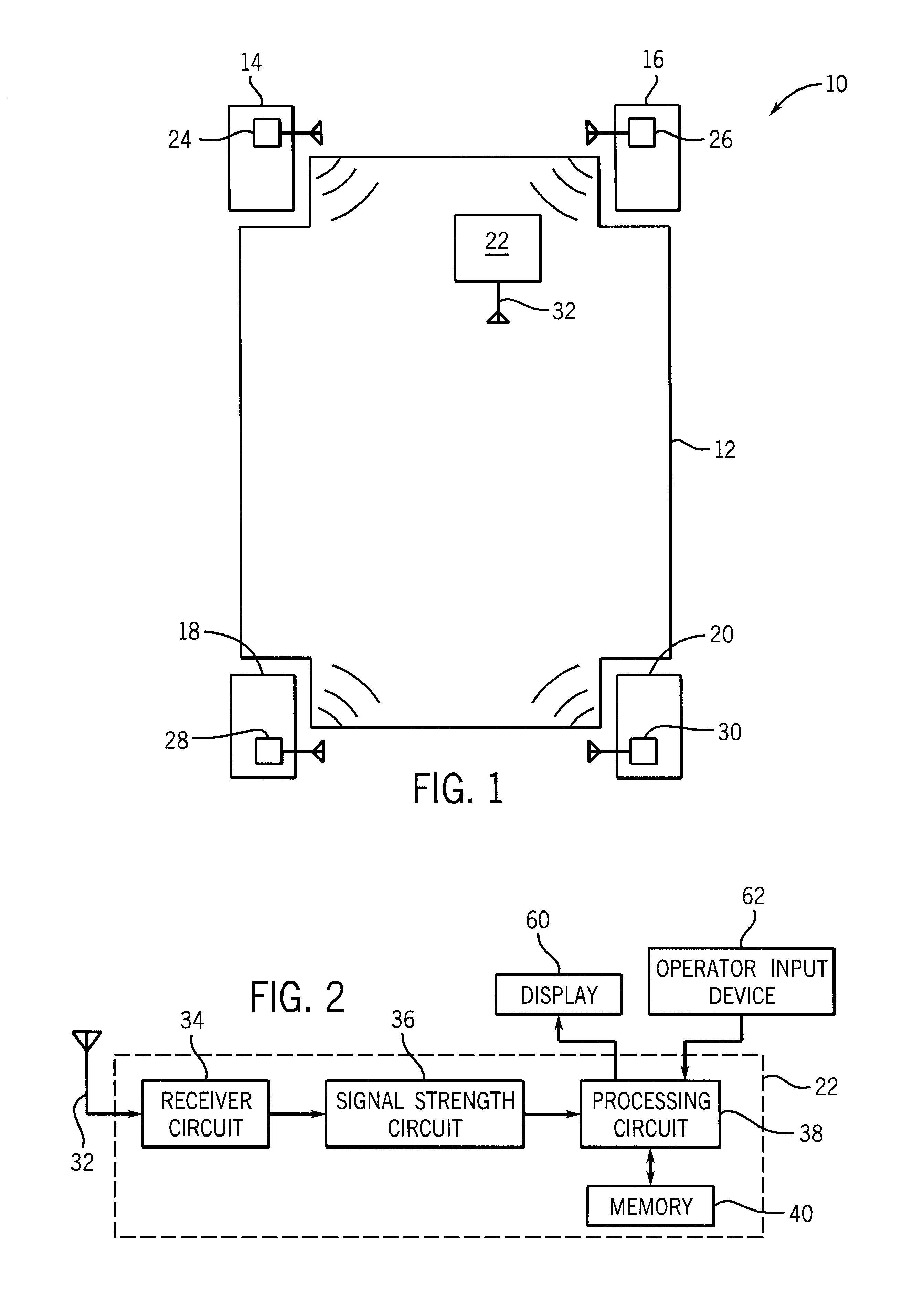
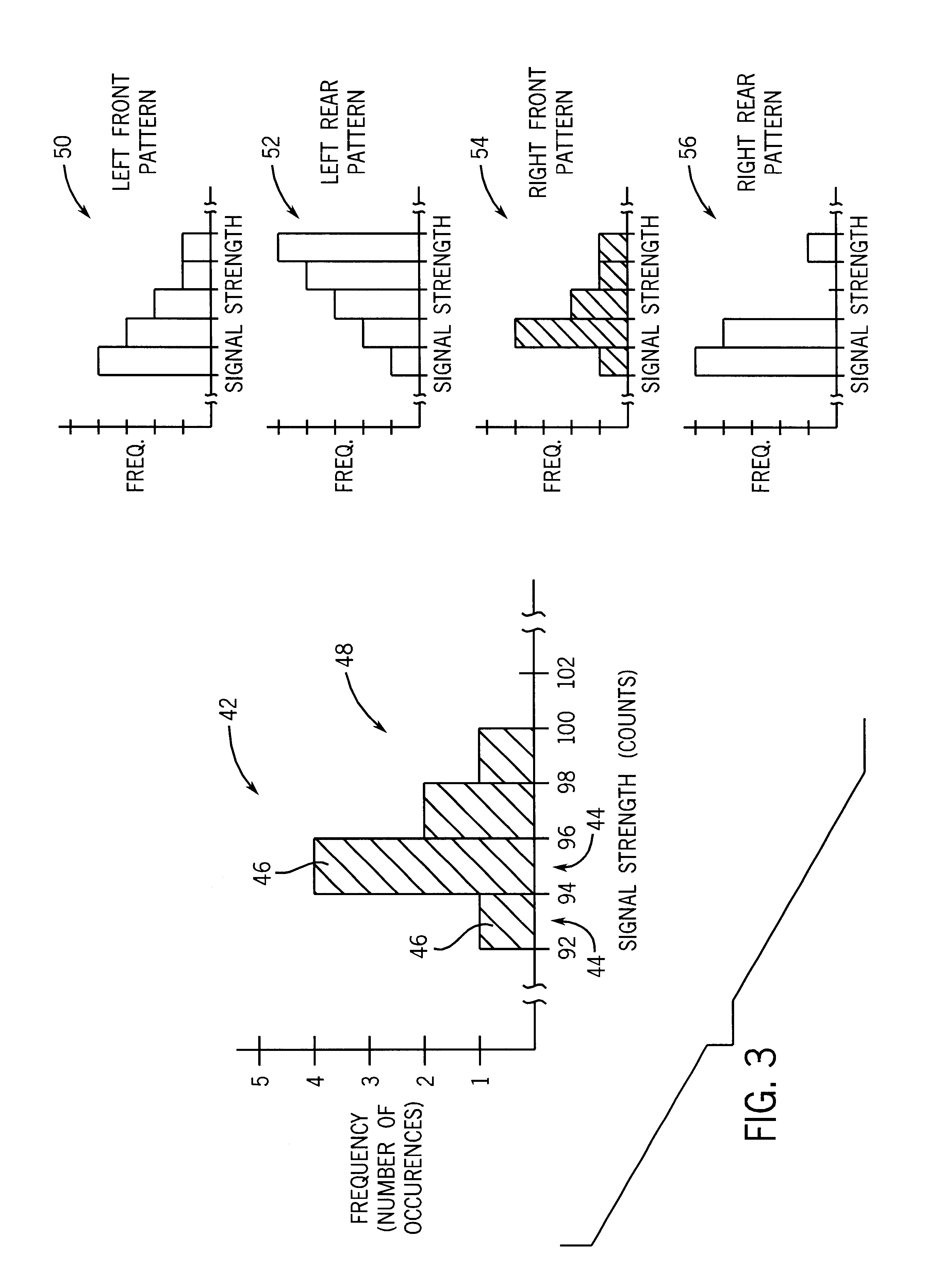
According to one exemplary embodiment, a method of identifying the position of a tire on a vehicle includes receiving a plurality of wireless messages from a transmitter associated with the tire and determining the signal strengths of the received wireless messages. The method further includes providing a frequency distribution of the wireless messages based on the signal strengths and comparing the frequency distribution to a predetermined frequency distribution to determine the position of the tire on the vehicle.

According to another exemplary embodiment, a system for identifying the position of a tire on a vehicle based on wireless messages received from the tire includes a receiver circuit, a signal strength circuit, a memory, and a processing circuit. The receiver circuit is configured to receive the wireless messages. The signal strength circuit is configured to determine the signal strengths of the wireless messages. The memory is configured to store a predetermined frequency...


PUM


Abstract

A system for identifying the position of a tire on a vehicle based on wireless messages received from the tire includes a receiver circuit, a signal strength circuit, a memory, and a processing circuit. The receiver circuit is configured to receive the wireless messages. The signal strength circuit is configured to determine the signal strengths of the wireless messages. The memory is configured to store a predetermined frequency distribution. The processing circuit is configured to provide a frequency distribution of the wireless messages based on the signal strengths and to compare the frequency distribution to the predetermined frequency distribution to determine the position of the tire on the vehicle.

Description

BACKGROUND OF THE DISCLOSUREIncreasing attention is being given to monitoring the pressure of tires on a vehicle while the vehicle is in motion. A typical tire pressure monitor includes a plurality of transmitter circuits coupled to each of a plurality of tires on a vehicle, each transmitter circuit including a tire pressure sensor inserted into the tire and a radio frequency transmitter. The transmitter circuits sense tire pressure and generate radio frequency signals in the form of a message, the message including a tire identification number and the sensed tire pressure. The tire pressure monitor also includes a receiver circuit coupled to the vehicle for receiving the radio frequency signals. The receiver circuit processes the signals by, for example, displaying the tire pressures of each tire, providing warnings when the tire pressures are outside predetermined parameters, etc.One challenge in tire pressure monitoring is identifying the location of the tires on the vehicle (e.g...

Claims


Application Information

Patent Timeline
Patent Type & Authority Patents(United States)
IPC IPC(8): B60C23/04B60C23/02
CPCB60C23/0416
Inventor HONECK, BRIAN S.OLSON, THOMAS R.UREEL, EMIL
Owner VISTEON GLOBAL TECH INC
Why Eureka
Try Eureka