Valve timing control device of internal combustion engine

a technology of timing control device and internal combustion engine, which is applied in the direction of valve arrangement, machines/engines, mechanical equipment, etc., can solve the problems of increasing the length of the engine, increasing the axially enlarged mounting space of the valve timing control device, and waste of electric power consumption of the vehicl

Inactive Publication Date: 2003-01-28
UNISIA JECS CORP
View PDF10 Cites 14 Cited by
  • Summary
  • Abstract
  • Description
  • Claims
  • Application Information

AI Technical Summary

Benefits of technology

That is, according to the present invention, there is provided a valve timing control device of an internal combustion engine, which can reduce or save an electric power consumed by an electromagnetic brake employed for applying an operation force to a movable control member of the valve timing control device.

Problems solved by technology

However, in the above-mentioned valve timing control device of the publication, due to the arrangement wherein the piston member is moved forward or rearward along the axis of the camshaft, the parts arranged at the front end of the camshaft need an axially enlarged mounting space thereof, which brings about an increase in length of the engine.
In fact, the electromagnets of the electric actuator arranged at an axially outside area of the piston member induce a major cause of the increase of the axially enlarged mounting space of the valve timing control device.
However, in some of them, usage of such electromagnetic brake has induced a wasteful electric power consumption of the vehicle.

Method used


Image

  • Valve timing control device of internal combustion engine
  • Valve timing control device of internal combustion engine
  • Valve timing control device of internal combustion engine

Examples


first embodiment

Referring to FIGS. 1 to 5 of the drawings, there is shown a valve timing control device 100 which is the present invention.

Although the valve timing control device 100 is described as being applied to intake valves of an internal combustion engine, the device 100 can be also applied to exhaust valves of the engine.

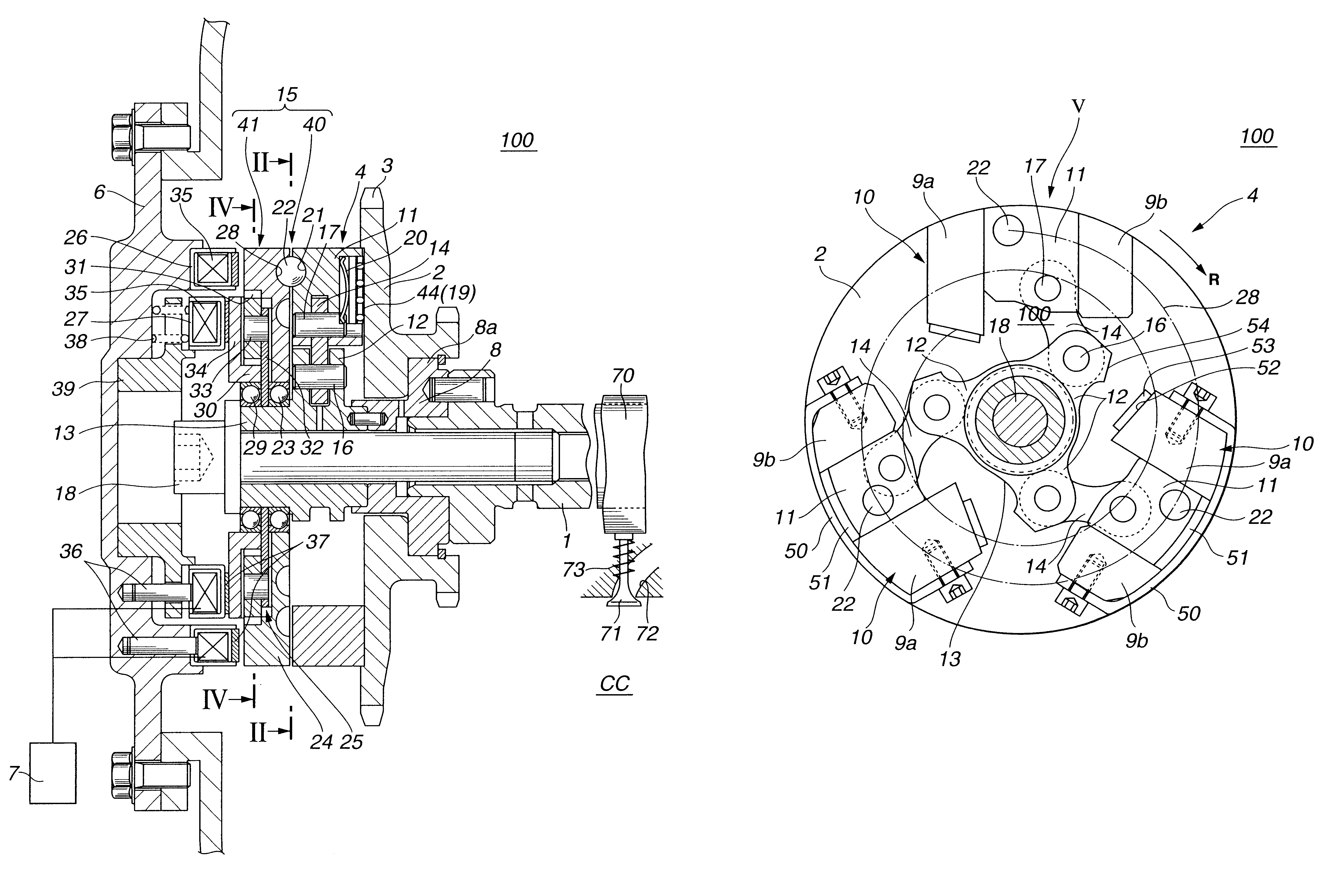
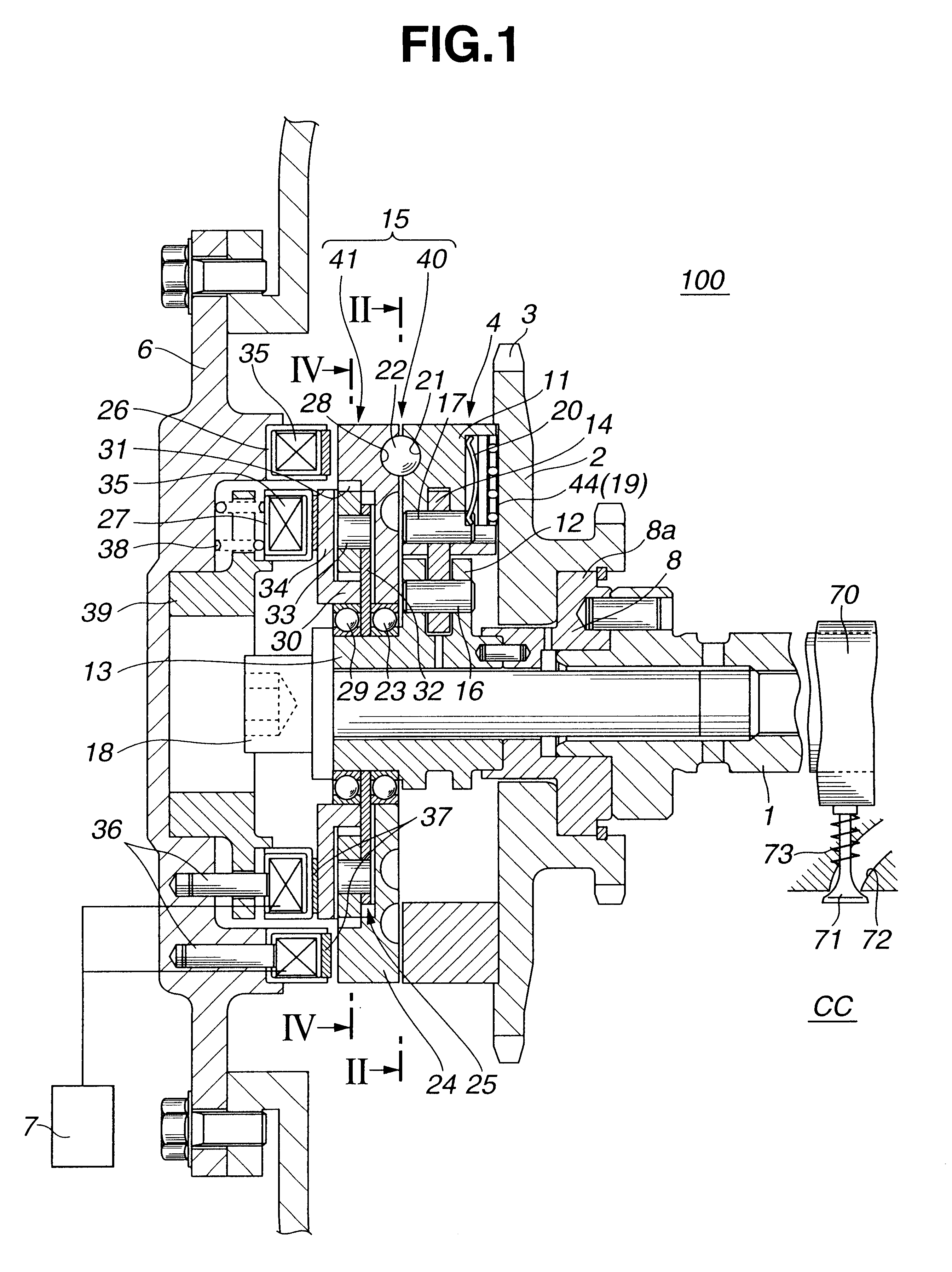
As is understood from FIG. 1, the valve timing control device 100 is arranged on a cylinder head which has a plurality of intake ports 72 (only one is shown) and a plurality of exhaust ports (not shown), each extending from an associated combustion chamber "CC" in a known manner. Each intake port 72 has an intake valve 71 which functions to open and close the intake port 72. Due to function of a valve spring 73, each intake valve 71 is biased in a direction to close the intake port 72. The intake valves 71 are driven by respective cams 70 provided on a camshaft 1 which is supported on the cylinder head in a manner to rotate about its axis.

Rotatably disposed around a front ...

second embodiment

Referring to FIG. 6, there is shown a valve timing control device 200 which is the present invention.

Since the second embodiment 200 is similar to the above-mentioned first embodiment 100, only parts or portions which are different from those of the first embodiment 100 will be described in detail in the following. Substantially same parts as those of the first embodiment 100 are denoted by the same numerals in FIG. 6.

As shown in FIG. 6, in this second embodiment 200, there is no means which corresponds to the spring 38 of the first embodiment 100.

That is, in this second embodiment 200, when the first and second electromagnetic brakes 26 and 27 are both in OFF condition, the friction pads 37 of the brakes 26 and 27 are released from the guide plate 24 and the brake flange 34 of the sun gear 30.

In order to shift the open / close timing of the intake valves 71 toward a retarded side, the second electromagnetic brake 27 is turned ON (viz., energized) and at the same time the first electr...

third embodiment

Referring to FIGS. 7 and 8, there is shown a valve timing control device 300 which is the present invention.

Similar to the above-mentioned second embodiment 200, substantially same parts as those of the first embodiment 100 are denoted by the same numerals in FIGS. 7 and 8.

In this third embodiment 300, in place of the planetary gear unit 25 employed in the first embodiment 100, a slide link mechanism 80 is employed.

The slide link mechanism 80 comprises a circular brake plate 81 which is rotatably disposed on a front end portion of the lever shaft 13 through a bearing 29, a circular carrier plate 82 which is secured to the lever shaft 13 at a position between the bearing 29 and another bearing 23, two shafts 83 which are provided at diametrically opposed portions of the circular carrier plate 82, each shaft being directed toward a VTC cover (6, see FIG. 1), two slide links 85 which are pivotally and respectively held by the two shafts 83 at their middle portions, each slide link havi...


PUM


Abstract

A drive rotation member is rotated about a given axis by a crankshaft of the engine, and a driven rotation member is rotated about the given axis together with a camshaft of the engine. A relative rotation angle control mechanism is arranged through which the drive and driven rotation members are coaxially connected. The relative rotation angle control mechanism has a movable control member which, when applied with an operation force from an actuation device, varies a relative rotation angle between the drive and driven rotation members. The actuation device comprises a first electromagnetic brake which applies an operation force to the movable control member to cause a rotation of the driven rotation member to be shifted in one of advancing and retarding directions with respect to a rotation of the drive rotation member, and a second electromagnetic brake which applies an operation force to the movable control member to cause the rotation of the driven rotation member to be shifted in the other of the advancing and retarding directions with respect to the rotation of the drive rotation member.

Description

1. Field of the InventionThe present invention relates in general to a control device for controlling operation of an internal combustion engine, and more particularly to a valve timing control device which controls or varies an open / close timing of intake and / or exhaust valves of the internal combustion engine in accordance with an operation condition of the engine.2. Description of the Related ArtIn order to clarify the task of the present invention, one valve timing control device of an internal combustion engine will be briefly described, which is shown in Laid-open Japanese Patent Application (Tokkai-hei) 10-153104.In the valve timing control device of the publication, a timing pulley driven by a crankshaft of the engine is rotatably disposed around a shaft member which is integrally connected to a camshaft. A so-called "relative rotation angle control mechanism" is arranged between the timing pulley and the shaft member. The relative rotation angle control mechanism comprises ...

Claims


Application Information

Patent Timeline
Patent Type & Authority Patents(United States)
IPC IPC(8): F01L1/344F01L1/352F01L1/34
CPCF01L1/352F01L1/34
Inventor WATANABE, MASAHIKO
Owner UNISIA JECS CORP
Why Eureka
Try Eureka