Optical disk label and method

Inactive Publication Date: 2003-01-28
SINGLESIGNON NET +1
View PDF14 Cites 19 Cited by
  • Summary
  • Abstract
  • Description
  • Claims
  • Application Information

AI Technical Summary

Benefits of technology

It is another object of the invention to provide a label for an optical disk which permits text and / or graphics to be placed over the hole in the center of the optical disk without interfering with the utility of the hole.
These and other objects of the present invention are achieved in the preferred embodiments disclosed below by providing a label for an optical disk of the type having a hole therethrough for being positioned onto a rotatable spindle by which the optical disk is rotated. The label comprises a sheet having a size and shape for being positioned on and adhered to the optical disk and overlying the hole. The sheet includes a plurality of slits formed therein for being positioned in registration with the hole in the disk when the label is positioned on the disk and defining between the slits a plurality of adjacent sheet segments for normally residing in the plane of the sheet and being deformable from the plane of the sheet in response to an object being extended into the hole, whereby the plurality of sheet segments can be provided with visual material while not interfering with the utility of the hole in the disk.
According to yet another preferred embodiment of the invention, a label is provided for an optical disk of the type having a hole therethrough for being positioned onto a rotatable spindle by which the optical disk is rotated, and comprises an integrally-formed web overlying the hole and including a plurality of slits formed therein defining between a plurality of adjacent web segments. The segments are deformable in response to an object being extended into the hole, whereby the plurality of web segments can be provided with visual material while not interfering with the utility of the hole in the disk.
According to yet another preferred embodiment of the invention, an optical disk of the type having a hole therethrough for being positioned onto a rotatable spindle by which the optical disk is rotated, is provided in combination with of a label formed of a sheet having a size and shape for being positioned on and adhered to the optical disk and overlying the hole, the sheet including a plurality of slits formed therein for being positioned in registration with the hole in the disk when the label is positioned on the disk and defining between the slits a plurality of adjacent sheet segments for normally residing in the plane of the sheet and being deformable from the plane of the sheet in response to an object being extended into the hole. The plurality of sheet segments can be provided with visual material while not interfering with the utility of the hole in the disk.
According to yet another preferred embodiment of the invention, a method is provided for producing an optical disk for being positioned onto a rotatable spindle by which the optical disk is rotated, and comprises the steps of forming a disk having a hole therein by which the disk is placed on and rotated by the rotatable spindle, forming an integrally-formed web overlying the hole, and forming a plurality of slits in the web for being positioned in registration with the hole in the disk and defining between the slits a plurality of adjacent web segments for being deformable in response to an object being extended into the hole, whereby the plurality of web segments can be provided with visual material while not interfering with the utility of the hole in the disk.
Referring now to FIG. 9, an optical disk 55 is shown in cross-section, and includes a hole 56 covered by an integrally-molded, very thin web 57 which serves as a substrate which can be silk-screened or otherwise provided with text or graphics material, or merely painted with a desired color. The web 57 is provided with slits 58 arranged in a pattern such as shown above. The slits 58 permit the adjacent segments 59 to be deflected upwardly by an object such as a spindle inserted through the hole 56, as described above. The thickness and thus the flexibility is determined empirically based upon the plastic material from which the optical disk is molded.

Problems solved by technology

The existence and necessity of the hole presents a significant disadvantage in the use of optical disks as advertising and promotional products, since the hole is relatively large in relation to the overall size of the disk, particularly in the smaller format disks and those with irregular shapes.

Method used


Image

  • Optical disk label and method
  • Optical disk label and method
  • Optical disk label and method

Examples


Embodiment Construction

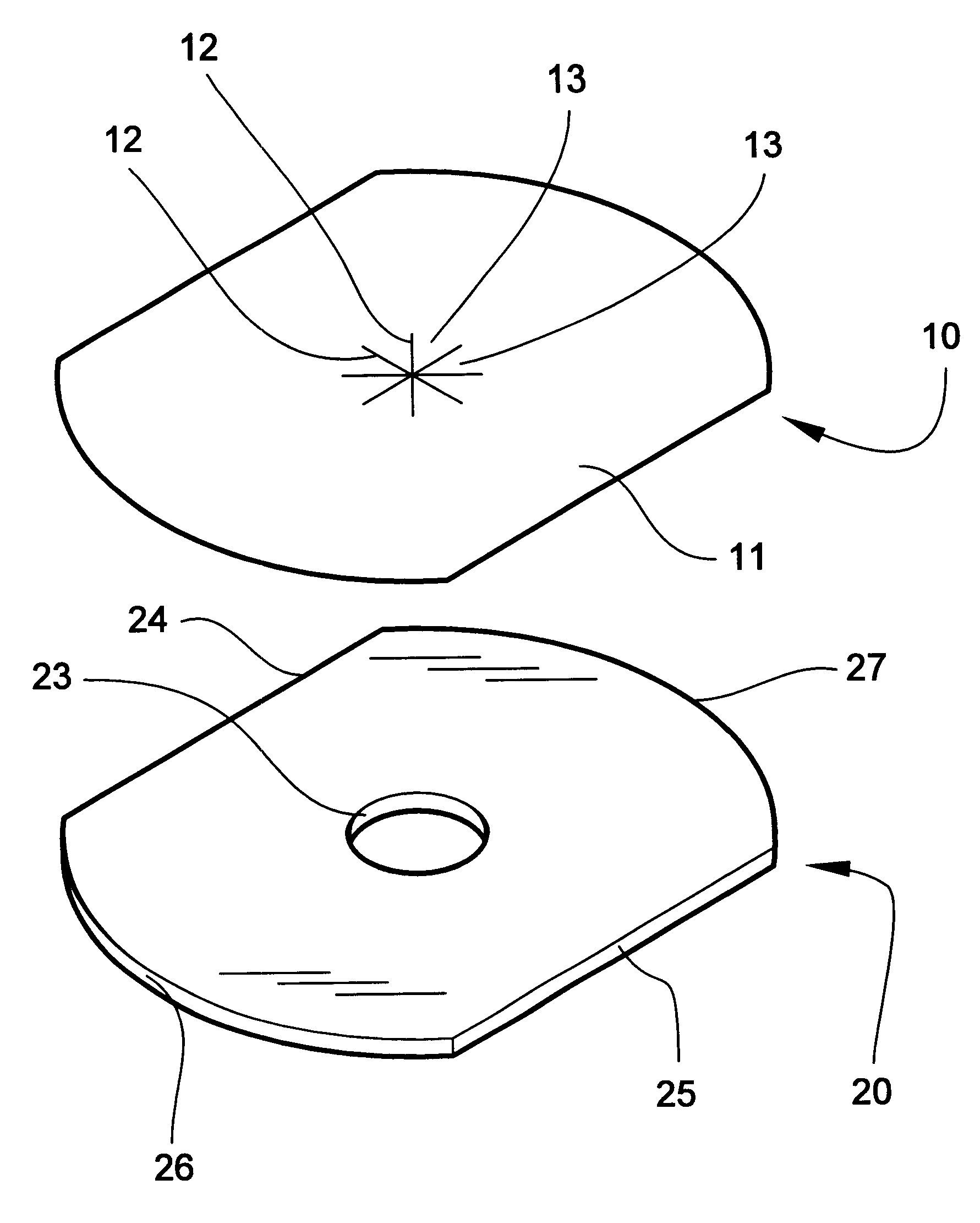
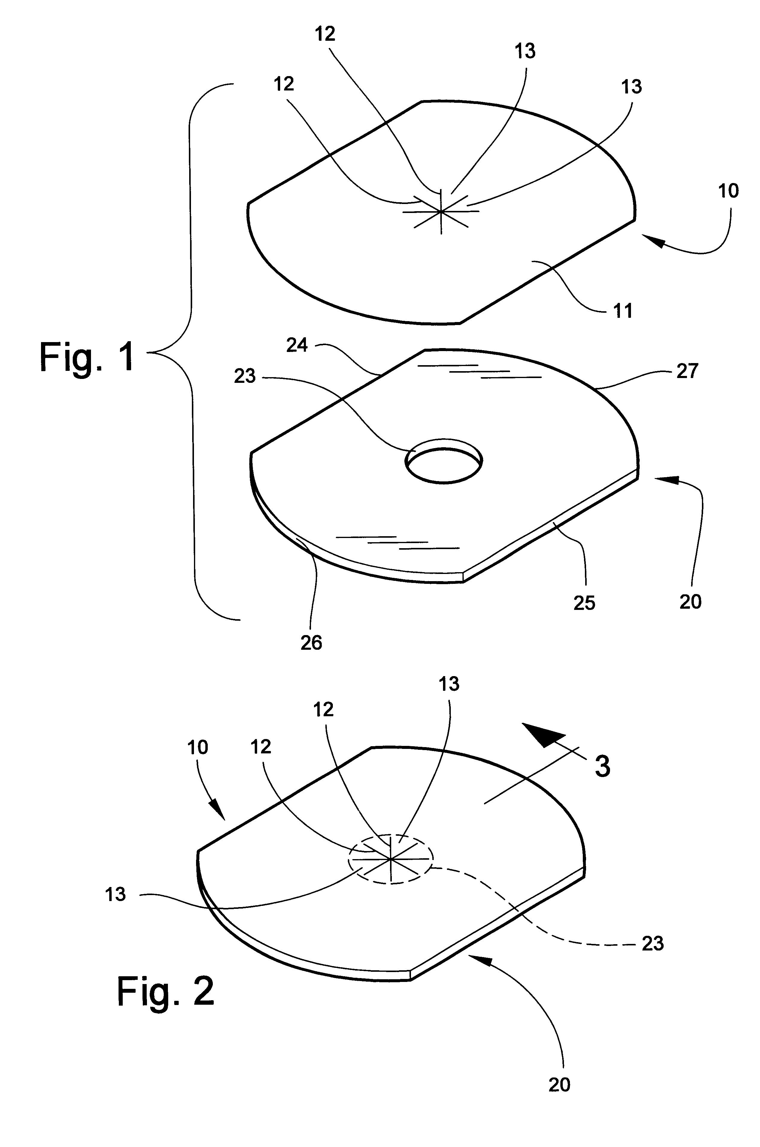
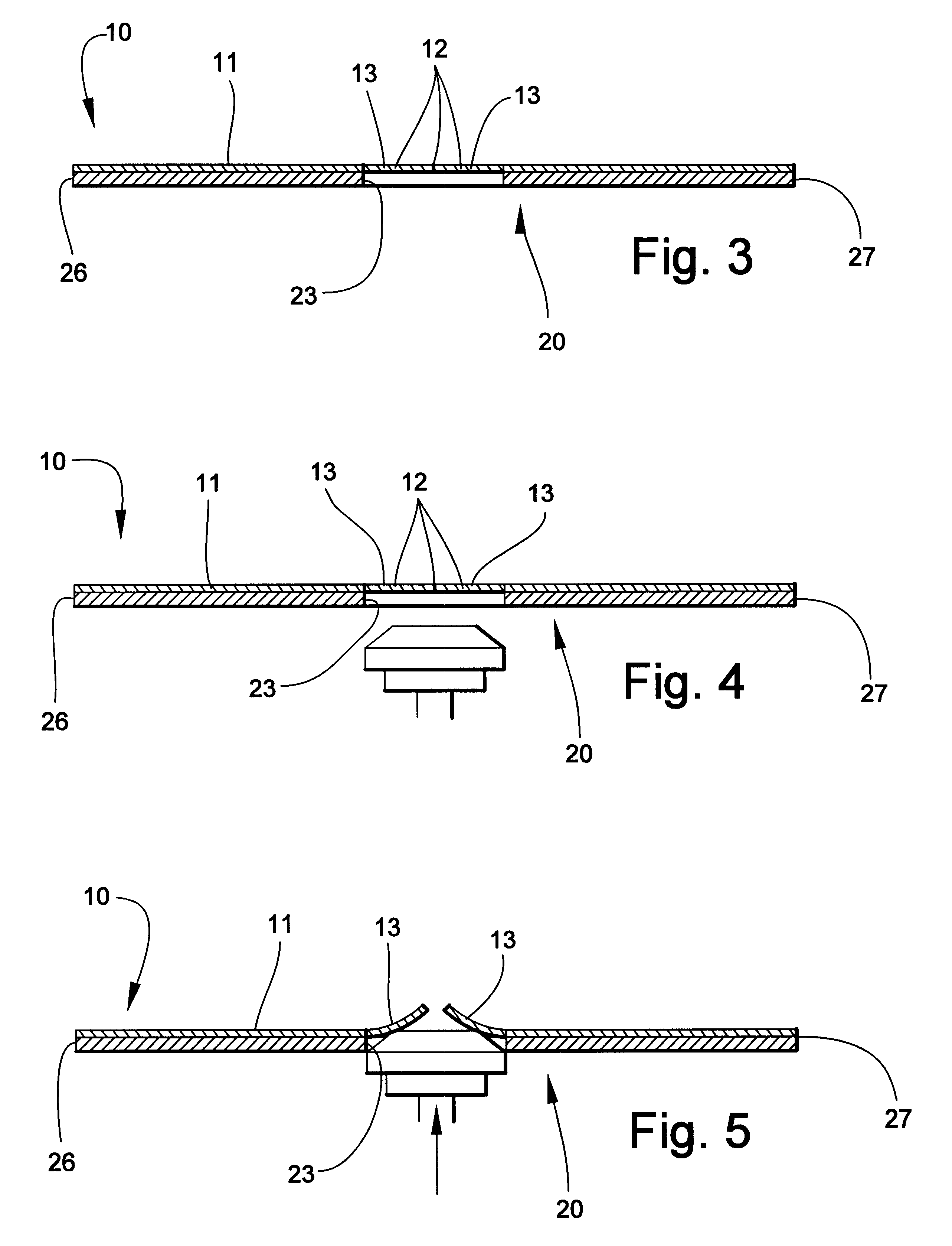
Referring now specifically to the drawings, a label according to the present invention is illustrated in FIG. 1 and shown generally at reference numeral 10. Label 10 is any suitable sheet material 11, such as paper or card stock, metal or plastic foil, or other plastic sheet material. Label 10 can be shaped to fit onto any optical disk of any size or shape. A plurality of slits 12 are formed in the sheet 11 and converge and intersect to form a star-shaped area defined by adjacent sheet segments 13. The slits 12 are placed in the label 10 in registration with the hole 23 so that when the label 10 is applied to the optical disk 20, the sheet segments 13 overlie the hole 23. The slits may be cut by any suitable method. As is shown in FIG. 2, the label 10 completely covers the hole 23 and renders it invisible. The slits 12 are only faintly visible, and lie in the plane of the sheet 11. This permits text and or graphics material to be placed on the label 10 without regard to the existenc...


PUM

PropertyMeasurementUnit
sizeaaaaaaaaaa
shapeaaaaaaaaaa
areaaaaaaaaaaa

Abstract

A label for an optical disk of the type having a hole therethrough for being positioned onto a rotatable spindle by which the optical disk is rotated. The label is formed of a sheet having a size and shape for being positioned on and adhered to the optical disk and overlying the hole. The sheet includes a plurality of slits formed therein for being positioned in registration with the hole in the disk when the label is positioned on the disk and defining between the slits a plurality of adjacent sheet segments for normally residing in the plane of the sheet and being deformable from the plane of the sheet in response to an object being extended into the hole, whereby the plurality of sheet segments can be provided with visual material while not interfering with the utility of the hole in the disk.

Description

TECHNICAL FIELD AND BACKGROUND OF THE INVENTIONThis invention relates to a label for an optical disk. Optical disks presently take many forms, and include plastic disks which contain digital data which may represent computer software, music, video, graphics and many other types of digital data. Such disks are presently made in many sizes and are referred to by different names, for example, CD's, compact disks, optical disks, DVD's, and include unrecorded disks which can be "burned" by consumers and disks which are capable of being recorded and then re-recorded. These disks are typically circular.Optical disks are also now made and sold which have irregular shapes, and are used for many purposes including business advertising. Such disks can be formed in virtually any shape so long as they will fit into and function in a disk player. One such shape commonly made and distributed is a "business card" disk, which comprises a optical disk which has been cut down in size so that two of th...

Claims


Application Information

Patent Timeline
Patent Type & Authority Patents(United States)
IPC IPC(8): G09F3/02G09F3/10G11B23/40
CPCG09F3/02G09F3/10G11B23/40Y10T428/24273Y10T428/218Y10T428/24314Y10T156/1052Y10T156/1064
Inventor CLARK, RICHARD LEE
Owner SINGLESIGNON NET
Why Eureka
Try Eureka