Rack for compact discs

a compact disc and rack technology, applied in the field of racks for compact discs, can solve problems such as difficulty in physically making a selection

Inactive Publication Date: 2003-02-18
THE SHARPER IMAGE
View PDF58 Cites 26 Cited by
  • Summary
  • Abstract
  • Description
  • Claims
  • Application Information

AI Technical Summary

Problems solved by technology

Where a large amount of CDs are stored it is difficult to physically make a selection.

Method used


Image

  • Rack for compact discs
  • Rack for compact discs
  • Rack for compact discs

Examples


Embodiment Construction

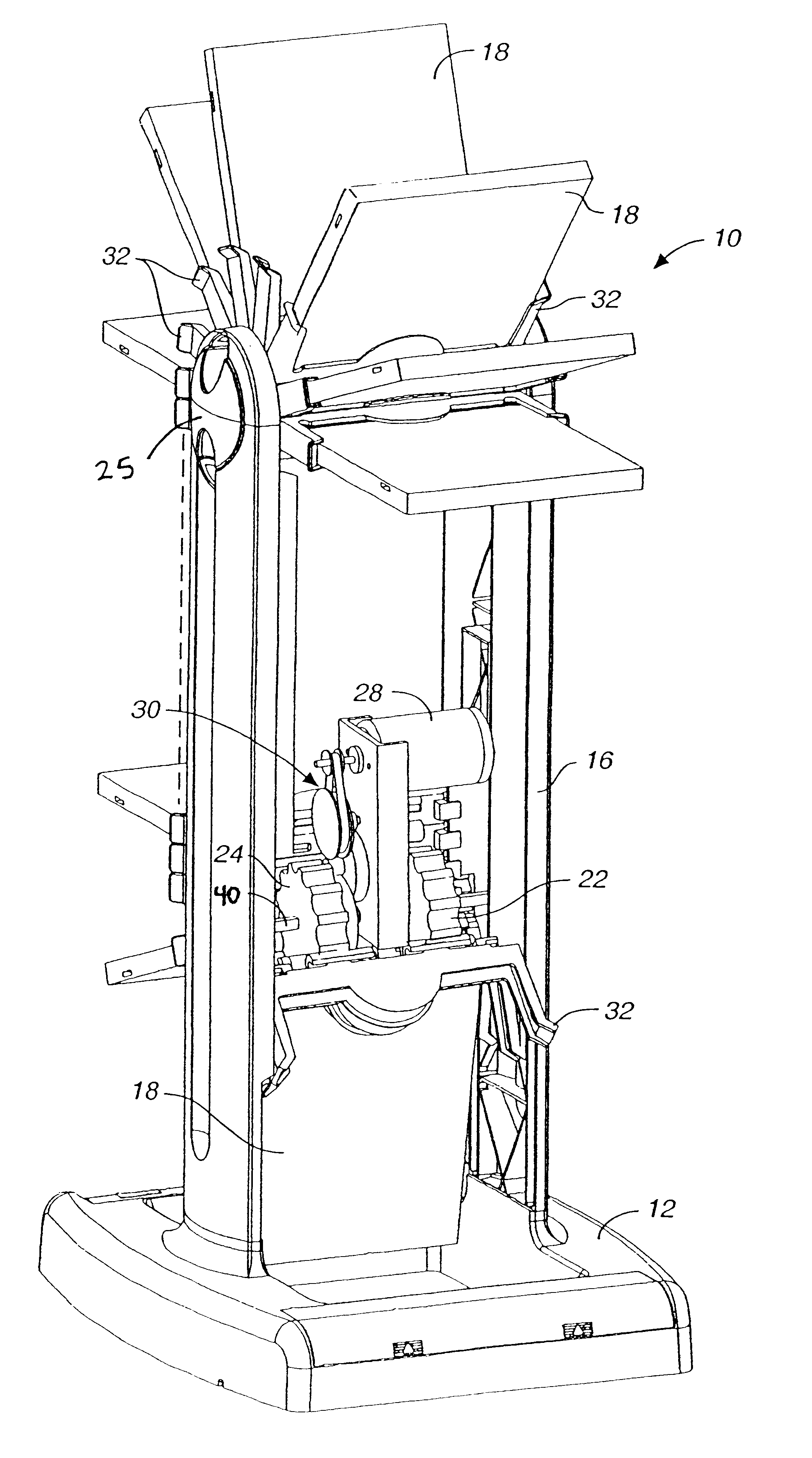
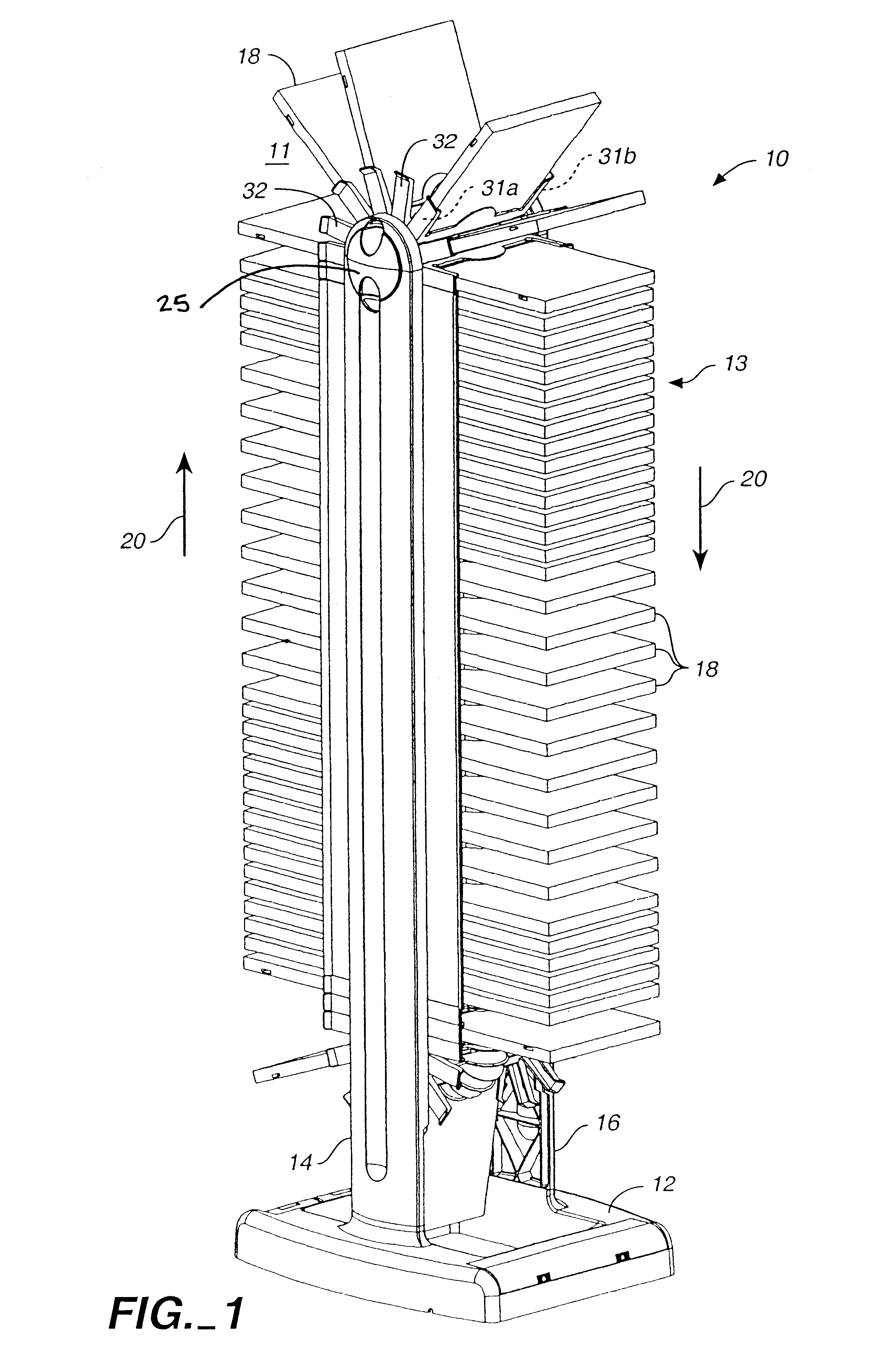
FIG. 1 is a perspective view of a rack embodying the present invention.

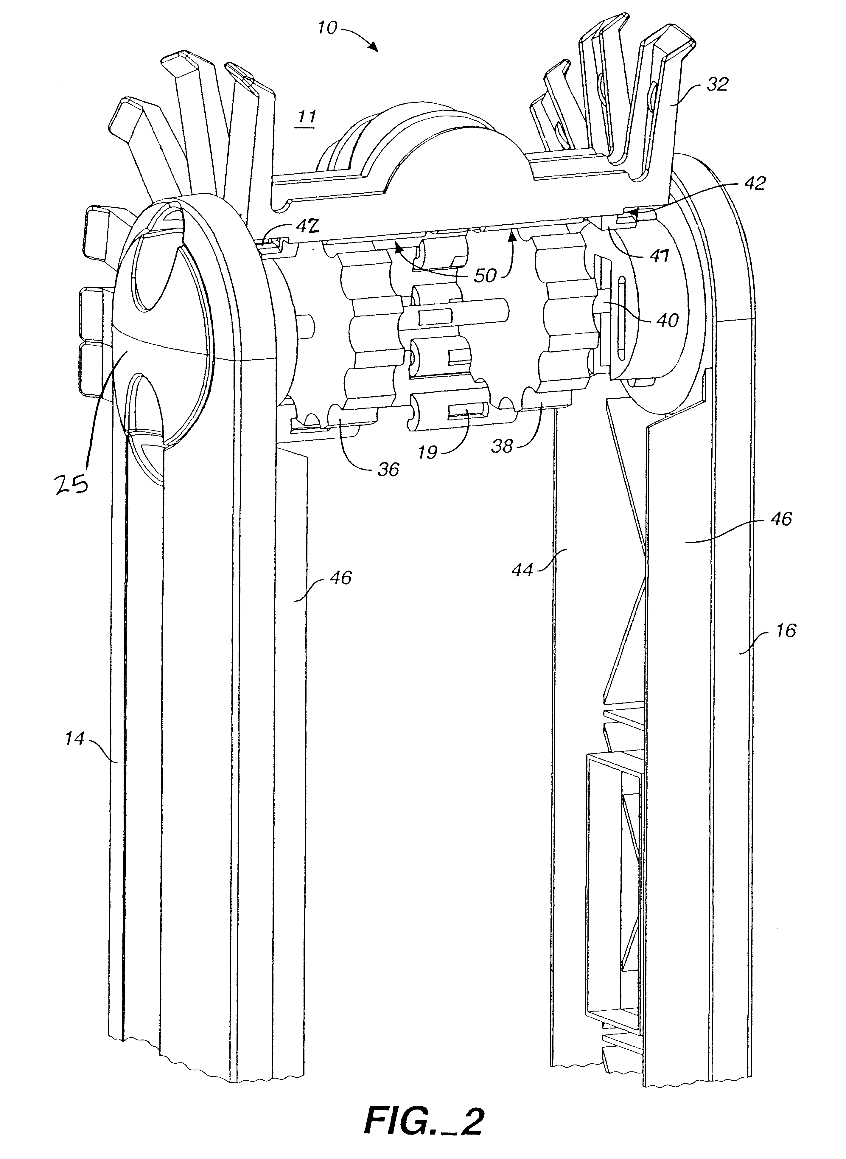
FIG. 2 is an enlarged detailed perspective view of an upper portion of the rack of FIG. 1.

FIG. 3 is an enlarged detailed view of a lower portion of the rack of FIG. 1.

FIG. 4 is a perspective view of a holder of the present invention shown in one view.

FIG. 4A is a side view of a container which would be held by the holder of FIG. 4.

FIG. 5 is a perspective of the same holder of FIG. 4 shown in another view.

FIG. 6A is a side elevation view illustrating several holders of FIGS. 4 and 5 coupled together.

FIG. 6B is a cross-sectional view of FIG. 6A.

FIG. 7 is side elevational view illustrating the holders of FIG. 6A as they would be rotated around a sprocket.

FIG. 8 is a cross-sectional view illustrating a holder of FIGS. 4 and 5 as it would retained in the rack of FIG. 1.

FIG. 9 is a perspective view similar to FIG. 1 which has been cut away to show the interior mechanism of the rack and its operation.

FIG. 10 is a perspe...


PUM

PropertyMeasurementUnit
thicknessaaaaaaaaaa
spaced-apart distanceaaaaaaaaaa
speedaaaaaaaaaa

Abstract

A motorized rack for holding the jewel cases or containers of CDs (or the CDs themselves) in a very compact manner includes a continuous loop formed of holders for the CD cases or other retainers which is driven by a pair of sprockets on which the holders are mounted for rotation. High density storage is provided by spacing the holders and their associated CD containers contiguously to one another and then removal is facilitated by allowing the holders and containers to fan out at the top the vertical tower for manual removal.

Description

The present invention is restricted to a rack for holding objects such as compact discs and other similar items. More specifically, where the rack is a motorized storage device for holding up to 100 compact discs (CDs) in their individual containers or so called jewel cases or more than 300 when special retainers are used.CD holders are well known which have no moving parts and which are in the form of vertical towers or horizonal cabinets. Where a large amount of CDs are stored it is difficult to physically make a selection. This is especially true for the lower part of a vertical tower. Thus it is desired to have a motorized type of CD storage device or rack to facilitate selection. It is also desirable to have a motorized rack which is very simple in design and stores the jewel cases or containers of the CDs (or the CDs themselves on retainers) in a very compact manner.OBJECT AND SUMMARY OF INVENTIONIt is therefore an object of the present invention to provide an improved rack fo...

Claims


Application Information

Patent Timeline
Patent Type & Authority Patents(United States)
IPC IPC(8): A47B81/06A47B63/00A47B49/00A47B63/06A47B81/00G11B33/04
CPCA47B49/002A47B63/065G11B33/0483G11B33/0466A47B81/068
Inventor CAPLAN, DAVIDTAYLOR, CHARLES E.
Owner THE SHARPER IMAGE
Why Eureka
Try Eureka