Light signaling device for floors

a technology for signaling devices and floors, applied in protective devices for lighting, lighting and heating apparatus, roof coverings, etc., can solve problems such as the inability to use lighted signalling on flat floor surfaces

Inactive Publication Date: 2003-02-25
HOFFMANN FRIEDEMAN
View PDF4 Cites 125 Cited by
  • Summary
  • Abstract
  • Description
  • Claims
  • Application Information

AI Technical Summary

Problems solved by technology

The devices described in both models are intended to signal uneven surfaces such as steps, stairs, etc., but cannot be used as lighted signalling on flat floor surfaces due precisely to the L-shaped configuration of the sections making up the device.

Method used


Image

  • Light signaling device for floors
  • Light signaling device for floors
  • Light signaling device for floors

Examples


Embodiment Construction

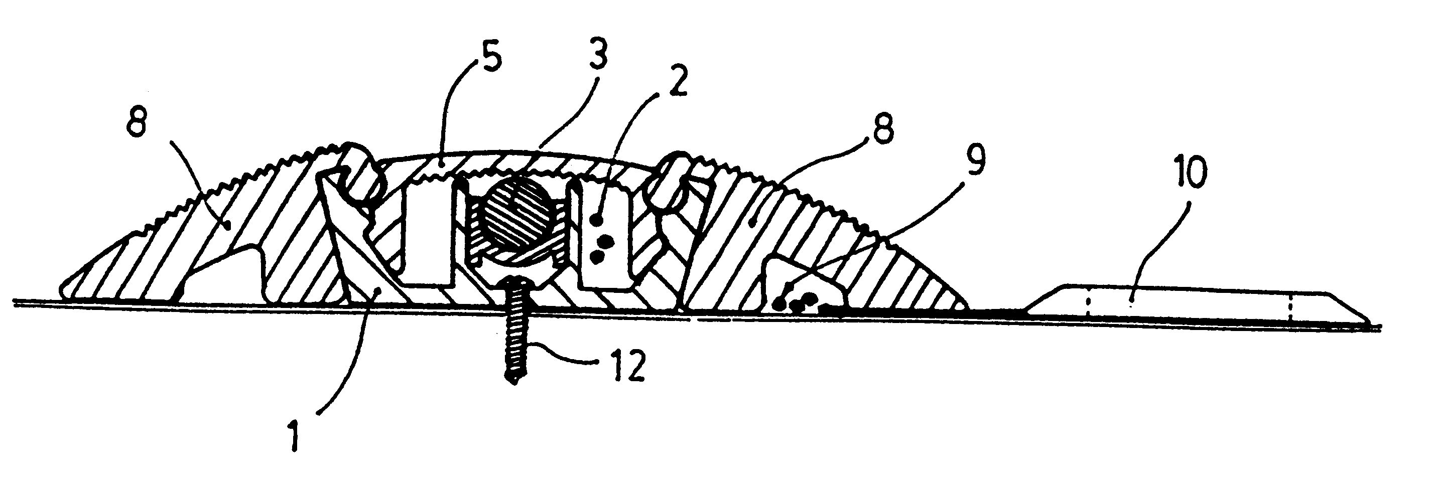
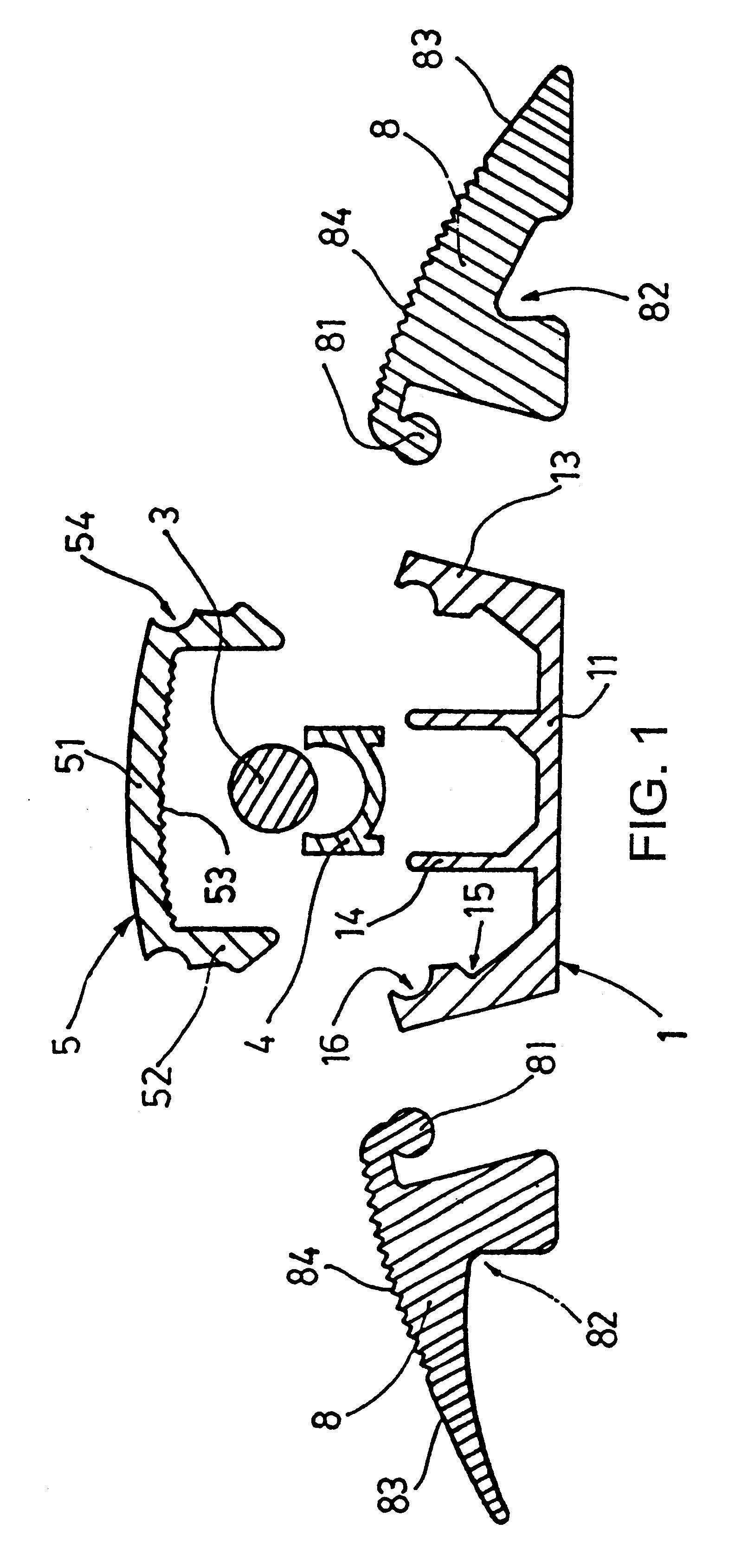
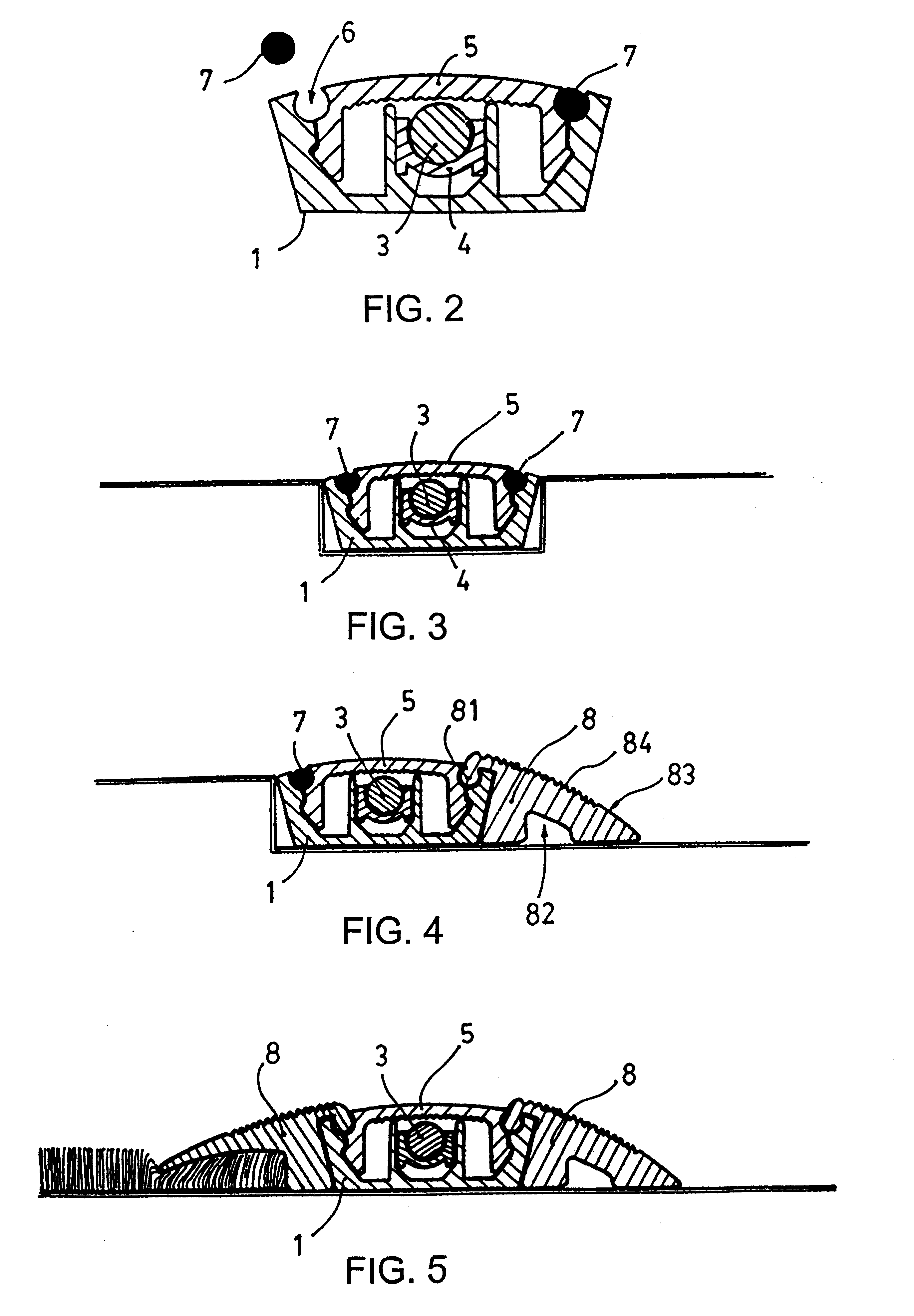
The lighted floor signalling device to which this invention refers presents certain constructive particularities designed to permit the signalling of flat floor surfaces such as both sides of a passageway, and may be built into the floor, protruding therefrom and holding down the ends of floor coverings such as rugs, carpeting, etc. with side wedges.

In accordance with the invention, the lighted floor signalling device consists of a U-shaped section composed of a flat base which is supported by and fastened to the floor area to be signalled and two wings on either end equipped with means to fasten the translucid guard by pressure.

On the inside of the lighted floor signalling device there are two ribs which start from the base and form a prismatic cavity for positioning the lighting means and their supports inside.

Between the inside lips and the side wings, the section is equipped with longitudinal cavities for running electrical, sound, telephone or any other type of wiring.

Inside th...


PUM


Abstract

A lit-up marking device for floors includes a section with a generally U-shaped layout defined by a flat base and by two end wings. Intermediate inlets for the pressure-fitting of a translucent protector are at the flat base. Lighting is positioned on a longitudinal support housed in the section and a translucent protector has a central portion and two side feet forming an arrow-head for fitting into the section. The wings of the section have, on their interior end, respective concavities which face concavities formed on the exterior in the initial zone of the side legs of the translucent protector. The cavities form one cavity with an opening for inserting optional elements for fixing the translucent protector onto the section.

Description

PURPOSE OF THE INVENTIONAs indicated by its title, this invention relates to a lighted floor signalling device of the type composed of a section intended to be mounted on the area of the floor to be signalled, lighting means mounted longitudinally inside the section and a translucid guard placed on top of the section which allows the light given off by the internal lighting means to shine through.BACKGROUND TO THE INVENTIONAs background to the invention, Utility Models 980269 and 9803048 both pertain to the applicant of this invention.Utility Model 9802069, which refers to a lighted section, is composed of an L-shaped section intended to be positioned on the vertex of a step, stair or any other uneven surface. This section contains a longitudinal cavity for housing the lighting means used to emit the light needed to signal the uneven surface.Utility Model 9803048 refers to certain improvements to the lighted floor signalling device for steps, stairs and the like which consists of an...

Claims


Application Information

Patent Timeline
Patent Type & Authority Patents(United States)
IPC IPC(8): E04F19/02H02G3/04H02G3/30E04F19/00F21S4/00F21S8/02F21V3/00F21V8/00F21V15/01F21V17/16F21V27/00F21Y101/00F21Y115/10G02B6/44
CPCE04F19/02F21S8/032F21V15/013F21V27/00G02B6/001G02B6/4459H02G3/0487H02G3/283H02G3/30F21S8/022E04F2011/1048F21V3/00F21V17/164F21W2111/02F21Y2101/02F21V3/02F21Y2101/00F21Y2115/10
Inventor HOFFMANN, FRIEDEMAN
Owner HOFFMANN FRIEDEMAN
Why Eureka
Try Eureka