Electrical connecting configuration

a technology of electrical connection and configuration, applied in the direction of coupling contact member, multi-conductor cable end piece, coupling device connection, etc., can solve the problems of preventing the two units from fitting together smoothly, insufficient dislocation absorption, and limited maximum dislocation absorption

Inactive Publication Date: 2003-03-04
SUMITOMO WIRING SYST LTD
View PDF9 Cites 39 Cited by
  • Summary
  • Abstract
  • Description
  • Claims
  • Application Information

AI Technical Summary

Problems solved by technology

In this configuration, even though the dimension error of each component and the attaching error of each unit are within the range of tolerance, this error accumulates when the two units are joined and consequently there is the danger of a larger dislocation appearing in position of the protruding terminals and the plate-shaped terminal fittings, thereby preventing the two units from fitting together smoothly.
However, with this method, the maximum extent of dislocation absorption is limited to the greatest bending capacity of the resilient clamping members, and there are cases where the dislocation absorption is insufficient.

Method used


Image

  • Electrical connecting configuration
  • Electrical connecting configuration
  • Electrical connecting configuration

Examples


Embodiment Construction

An embodiment of the present invention is explained below with the aid of FIGS. 1 to 6.

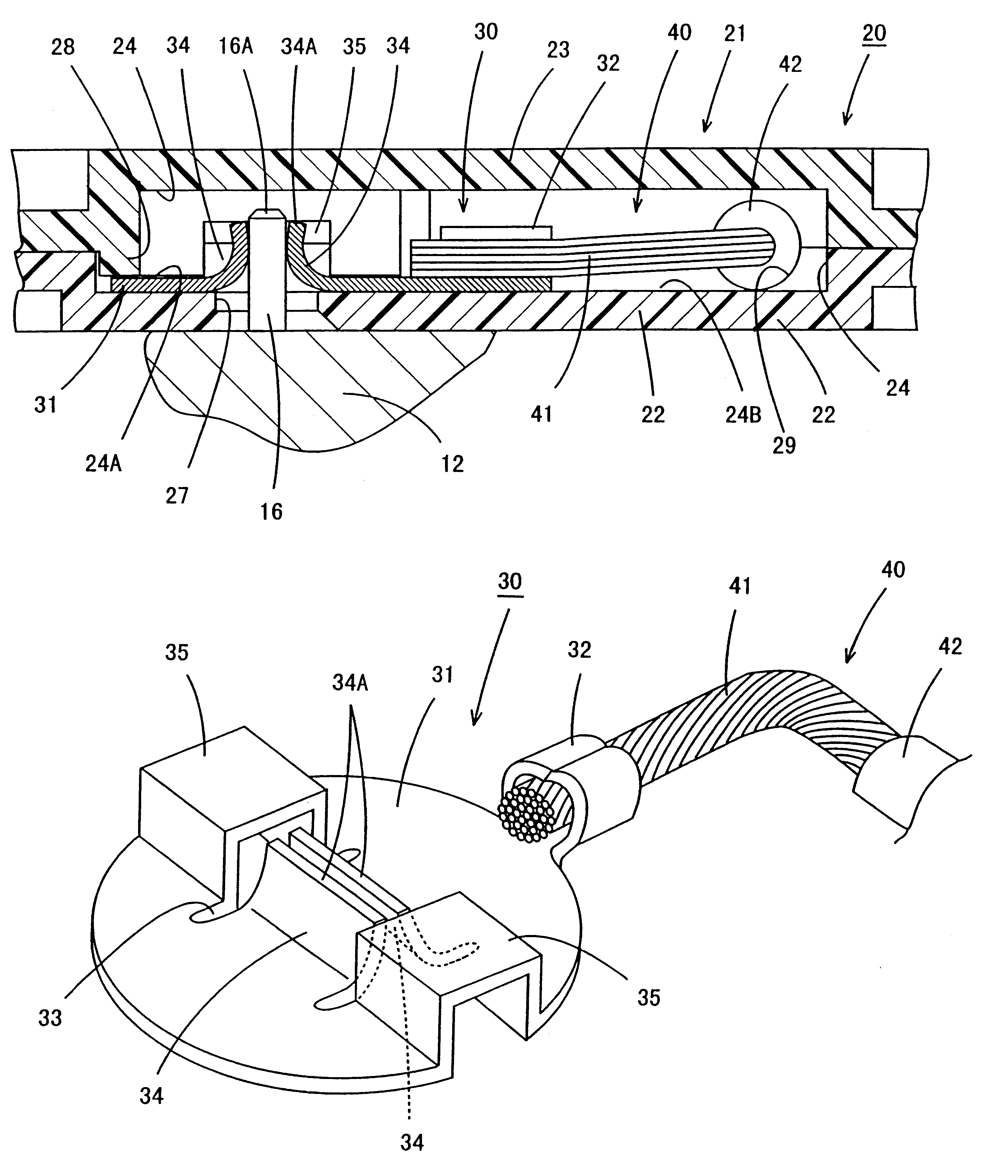
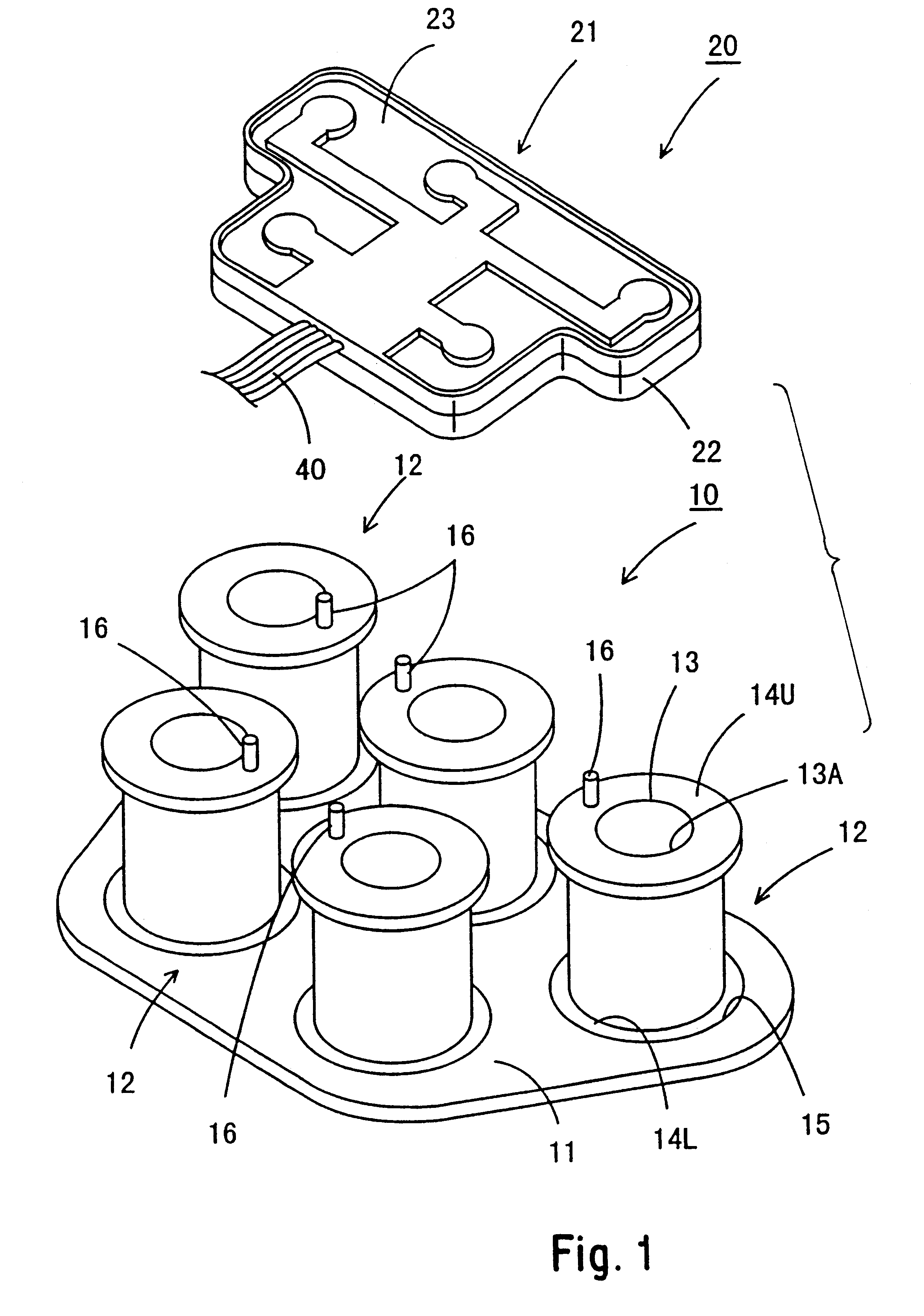
In the present embodiment, a solenoid unit for controlling oil pressure is provided within a gearbox casing of an automatic transmission of an automobile. This solenoid unit comprises a coil unit 10 and a connector 20 for providing electricity to the coil unit 10. When the connector 20 is joined to the coil unit 10 within the gearbox casing, the coil unit 10 and the connector 20 reach an electrically connected state. The connector 20 is connected to a wire harness via an interrupted connector which passes through the gearbox casing, this connector 20 providing electricity from a battery to each coil 12 of the coil unit 10.

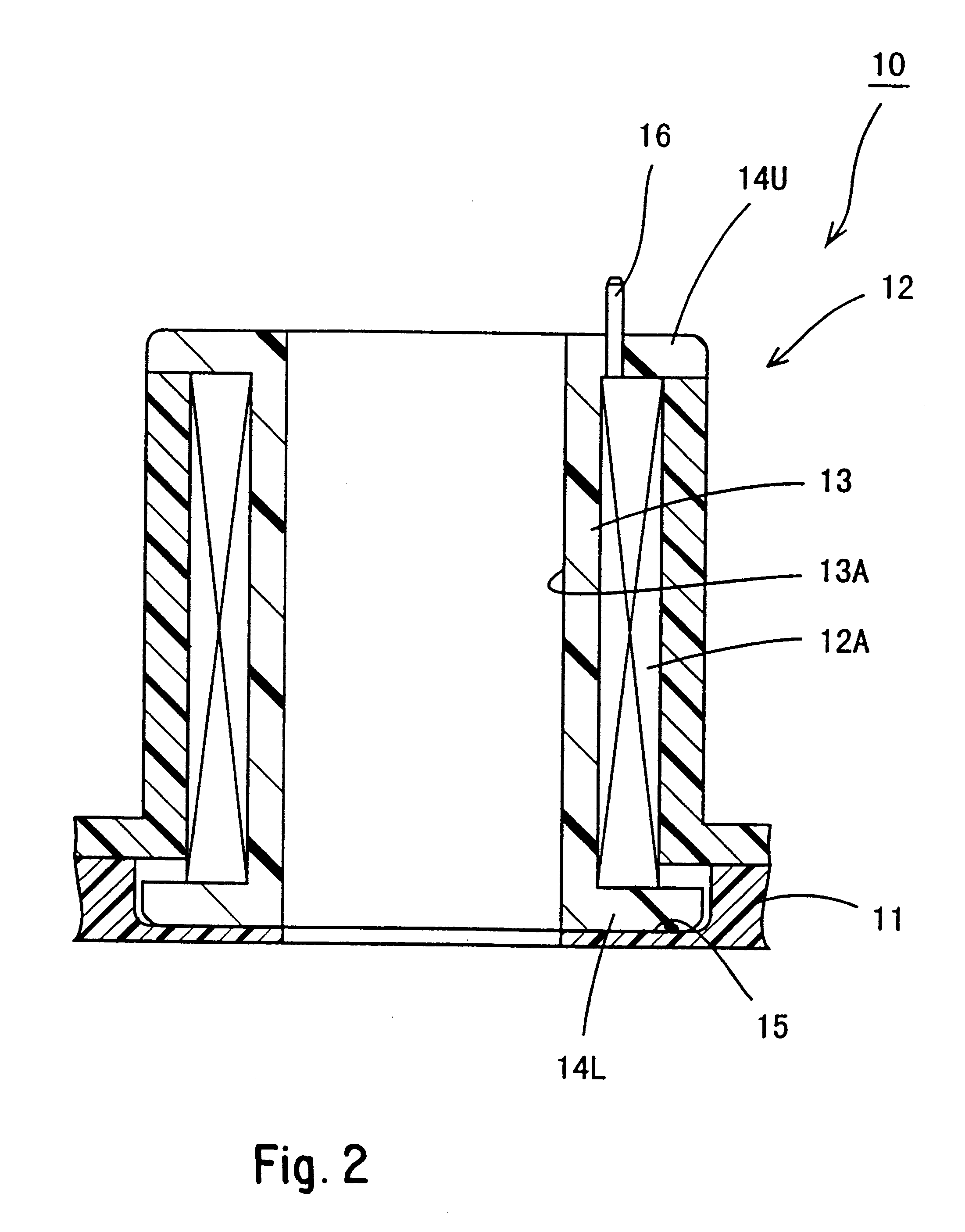
The coil unit 10 comprises a trapezoidal plate-shaped base plate 11. A plurality of coils 12 (five in the present embodiment) are distributed in specified locations on an upper face thereof, and are fixed thereto. Each coil 12 comprises wires 12A wound around the outer circumfere...


PUM


Abstract

Terminal fittings 30 are capable of moving in a direction perpendicular to a direction of joining of a coil unit 10 are located on a connector unit 20. Electric wires 40 have portions insulation 42 thereof removed, thus exposing conducting wires 41 which lie on a bent path. If terminal members 16 and terminal fittings 30 show a dislocation in position when the two units 10 and 20 are to be joined together, the exposed portion of the conducting wires 41 bends, and the terminal fittings 30 change position, thereby correcting the dislocation in position and allowing the terminal members 16 to fit without hindrance.

Description

The present invention relates to an electrical connecting configuration for a coil unit provided with a plurality of coils distributed in specific locations and a connector unit provided with connecting members distributed so as to correspond with the coils.BACKGROUND TO THE INVENTIONA solenoid unit for controlling oil pressure is provided within a gearbox casing of an automatic transmission of an automobile. A connector unit attached to a wire harness outside the gearbox casing provides electricity to coils of this solenoid unit. An example of this connector unit is described in the laid open publication JP-9-55235. The solenoid unit thereof is provided with a coil unit having a plurality of coils distributed at specified locations on a base, these coils being fixed thereto, each of the coils being provided with a separate protruding terminal. The connector unit thereof has a plurality of plate-shaped terminal fittings distributed on the base so as to correspond to each of the coil...

Claims


Application Information

Patent Timeline
Patent Type & Authority Patents(United States)
IPC IPC(8): H01R4/48H01R11/12H01R11/11H01R13/11H01R13/642
CPCH01R4/4809H01R11/12
Inventor MUTA, JUNJIITO, KATSUYA
Owner SUMITOMO WIRING SYST LTD
Why Eureka
Try Eureka