User interface for selecting functions in an electronic hardware

Inactive Publication Date: 2003-05-06
CLOTHING PLUS OY
View PDF10 Cites 116 Cited by
  • Summary
  • Abstract
  • Description
  • Claims
  • Application Information

AI Technical Summary

Benefits of technology

We have now invented, according to the independent claims, a user interface, an electronic hardware arrangement, a control system for

Problems solved by technology

The use of a mouse is restricted by the fact

Method used


Image

  • User interface for selecting functions in an electronic hardware
  • User interface for selecting functions in an electronic hardware
  • User interface for selecting functions in an electronic hardware

Examples


Embodiment Construction

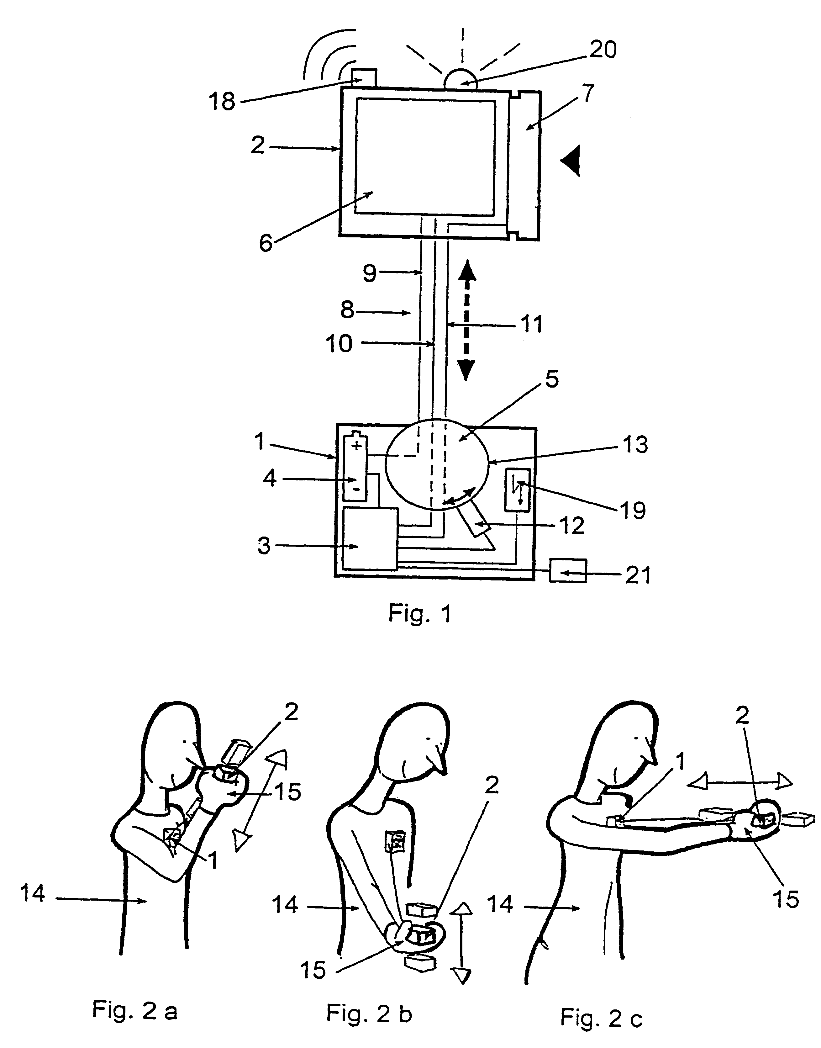
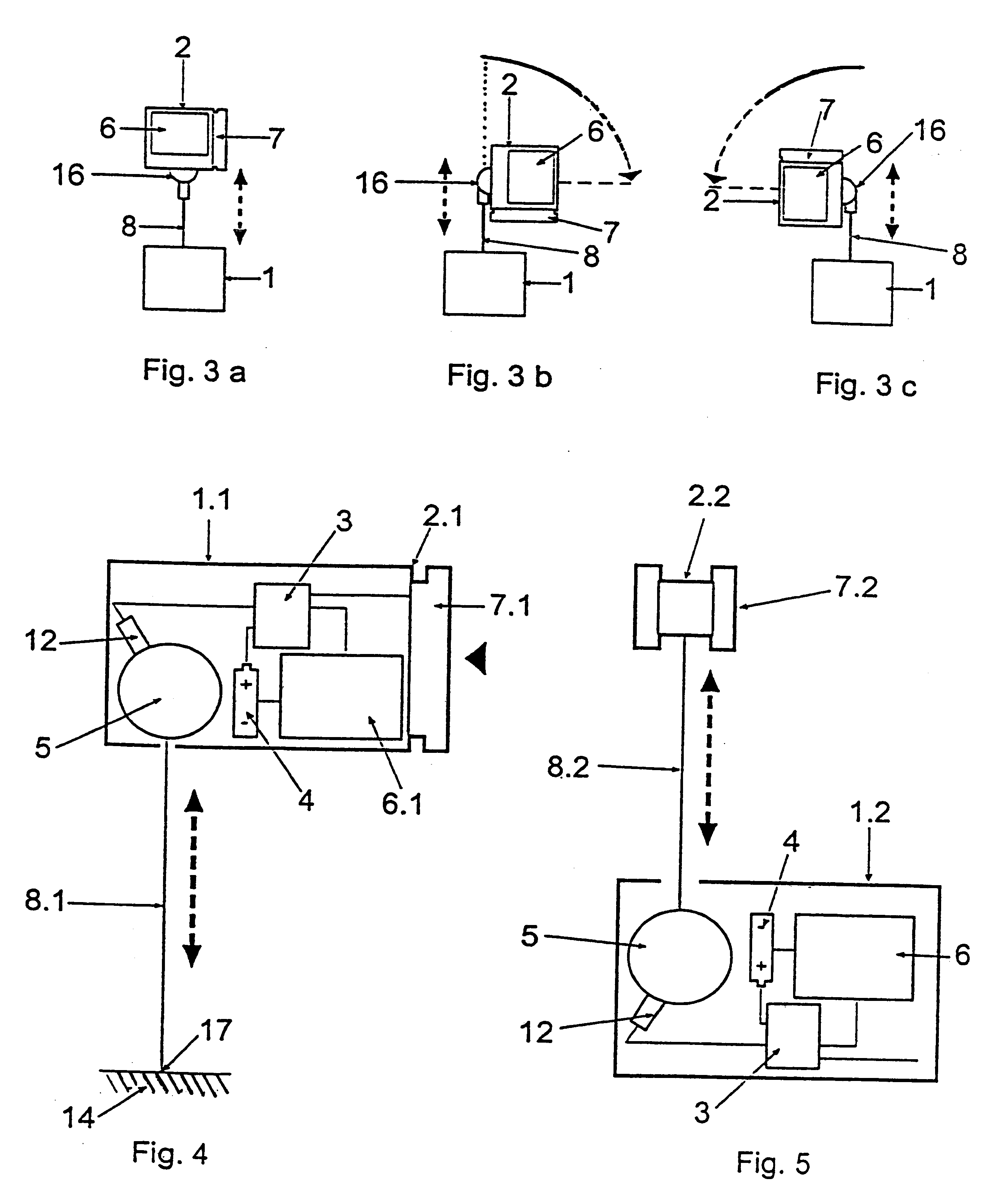
The arrangement according to FIG. 1 comprises a computer unit 1 and a connected mobile operating device 2. The computer unit includes a processor 3, a power source 4 and a spring-loaded coil 5. The operating device comprises a display 6 and a press key 7 for controlling the computer. On the coil, there is wound a cable 8, the other end whereof is attached to the coil and the other end to the operating device. The cable is provided with wires for the connections required by the display and the computer, for example a current wire 9, a display signal wire 10 and key signal wires 11. From the coil, the wires are connected by sliding switches to wires leading to the power source and the processor. The coil also includes a revolution counter 12, which is connected to the processor. The processor registers at suitable steps, for instance after every complete revolution, the rotary motion of the coil and at the same time the stepwise measured distance of the operating device from the compu...


PUM


Abstract

The invention relates to a user interface in an electronic hardware arrangement, with an operating device for starting the desired function. The operating device has a fixing point, from which its distance can be adjusted, and means for defining said distance. The function to be performed in each case depends on the defined distance. The invention can be used for instance in portable computers.

Description

The invention belongs to the field of controlling electronic hardware arrangements and relates to a user interface of an electronic arrangement, whereby said arrangement can be controlled. In particular, the invention can be employed in applications where the use of a keyboard is cumbersome or impossible. One application for the invention are data processing devices, such as portable computers.DESCRIPTION OF THE PRIOR ARTA computer is usually controlled by means of a keyboard. The number of required keys is normally fairly large. In order to press the keys, there are needed free fingers or a pin of some kind. A computer can be controlled by means of so-called menus, where the operative alternatives available in each situation are represented at various locations on the display screen. The desired function is selected by shifting the cursor on the screen to the function in question, and started by pressing the enter key.Another generally used computer operating device is a so-called ...

Claims


Application Information

Patent Timeline
IPC IPC(8): G06F1/16G06F3/0346G06F3/033
CPCG06F1/1615G06F1/1626G06F1/163G06F1/1683G06F1/1684G06F1/1637G06F2200/1637
Inventor IMPIO, JUSSI MARKUS
Owner CLOTHING PLUS OY
Why Eureka
Try Eureka