Automobile door mirror

a door mirror and automobile technology, applied in the field of door mirrors, can solve the problems of inability to meet the needs of automobiles, the difficulty of employing the shaft of the common automobile, and the inability to increase the productivity of the door mirror

Inactive Publication Date: 2003-05-13
MURAKAMI CORP
View PDF6 Cites 10 Cited by
  • Summary
  • Abstract
  • Description
  • Claims
  • Application Information

AI Technical Summary

Problems solved by technology

Thus, it has been difficult to employ the shaft in common among automobiles of the types.
Consequently, the conventional door mirror has a drawback in that the productivity thereof is not increased.
Further, because the strength of the stopper is determined according to the material thereof, it is difficult to select the material of the shaft.
That is, a load imposed on the stopper is large owing to a moment produced at the mounting position thereof.
Consequently, it is difficult to form the stopper from a resin.
However, it is understood that when the convex rotation restricting member and the base are integrally formed, the stopper may be deformed or damaged by a collision with or the application of a shock thereto during turning of the door mirror, and thus, the stopper cannot perform essential functions.

Method used


Image

  • Automobile door mirror
  • Automobile door mirror
  • Automobile door mirror

Examples


Embodiment Construction

Embodiments of the invention are concretely described hereinbelow with reference to the accompanying drawings.

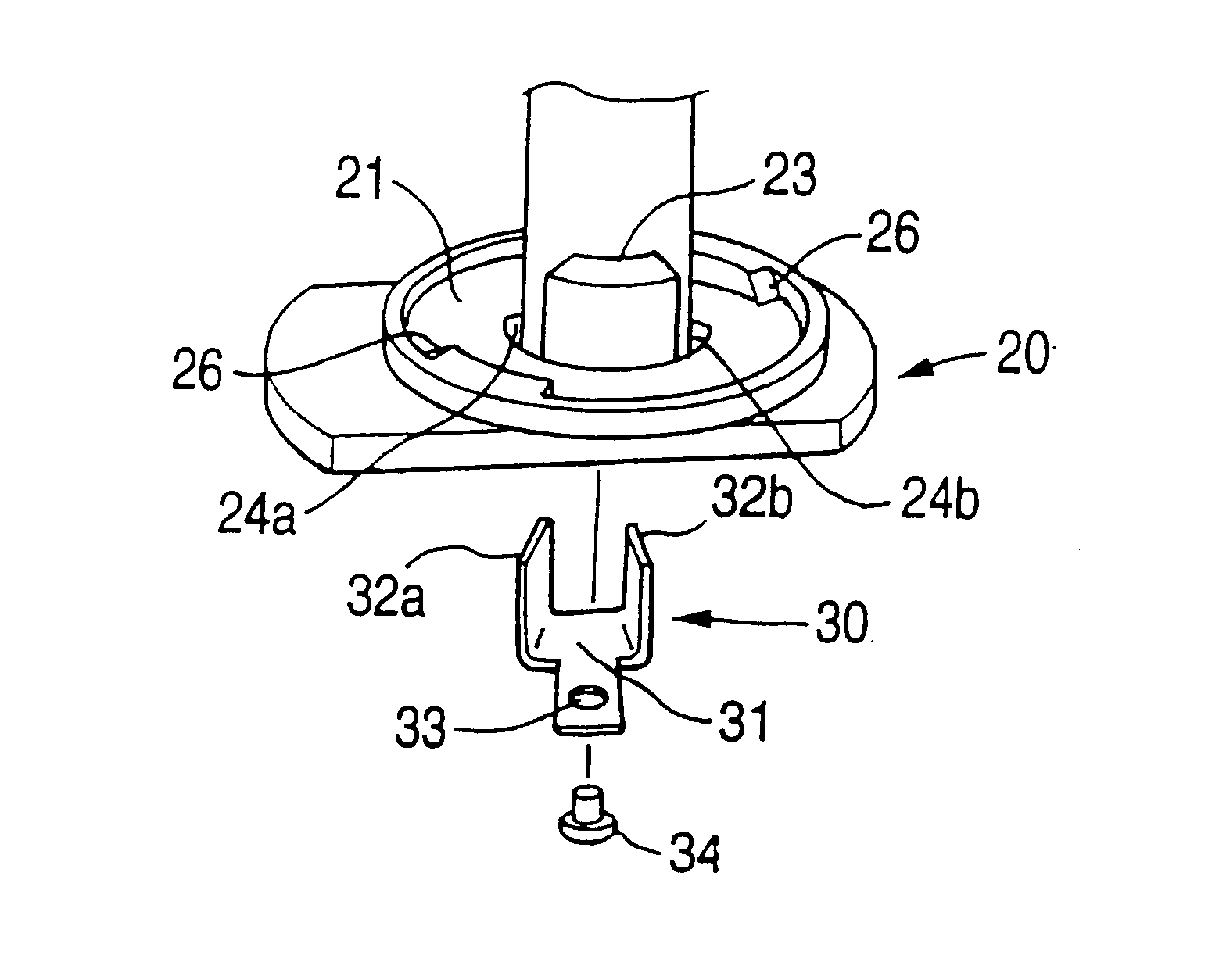
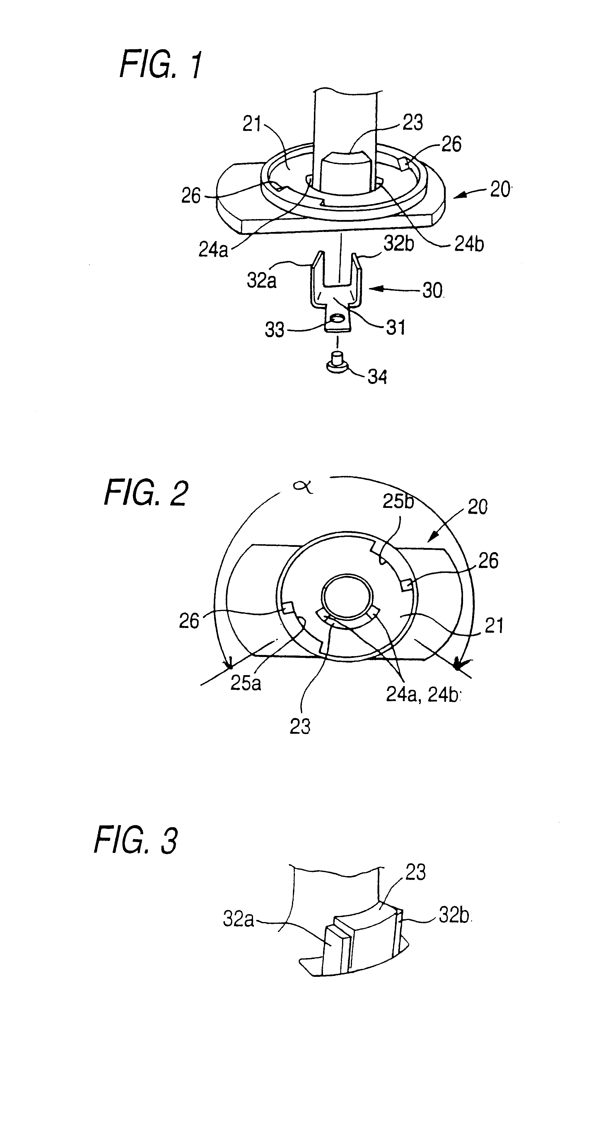
FIGS. 1 to 3 illustrate an embodiment of the invention. Incidentally, these figures exemplarily illustrate a shaft of a right-hand side (that is, R-side) door mirror between a left-hand side door mirror and the right-hand side door mirror. FIG. 1 is a perspective view thereof. FIG. 2 is a view thereof taken from above. Additionally, the illustration of a shaft of an L-side door mirror is omitted.

In FIGS. 1 and 2, reference character 20 designates a shaft, and 21 denotes a shaft base portion. This base portion 21 and a circularly arcuate projection 23 for restricting a folding angle of a frame are integrally formed. This projection 23 is preliminarily formed in such a way as to have a predetermined certain size corresponding to a minimum folding angle of the door mirror. Further, a set of through holes 24a and 24b are formed on both sides of this projection. Incidentally, ref...


PUM


Abstract

A rotation restricting structure of an automobile door mirror, in which a shaft is erected on the top surface of a projection portion of a mirror base, and in which a frame for supporting a mirror body is turnably fitted onto the shaft, wherein a stopper member for restricting a turning angle by engaging with the frame is provided between the frame and the shaft. The stopper member includes a projection, which is formed on the shaft base portion in such a way as to be integral therewith, and an angle adjusting plate provided separately from the projection. The adjusting plate having a thickness corresponding to a folding angle of the door mirror is attached to each or one of both the opposite side surfaces of the projection. Thus, even when the folding angle of the mirror body is changed, the frame and the shaft can be used in common among the door mirrors. Moreover, the strength of the stopper can be increased.

Description

This invention relates to an automobile door mirror. More particularly, the invention relates to a door mirror constructed by providing a positioning member on a shaft serving as a rotating shaft of a body mirror in an electrically driven housing type mirror or foldable type mirror adapted to turn the mirror body between an erected position (i.e., a position when in use) and a housed position (i.e., a folded position).An automobile door mirror has a configuration in which a mirror body is attached to a mirror base projecting from an outer plate of a vehicle. Recent door mirrors ordinarily employ a configuration in which a mirror body is driven in such a manner as to rotate around a spindle between the used position (i.e., a neutral position) and the housed position. When placed in the housed position, or when having a configuration adapted so that when an external force or shock is applied to the mirror body, the mirror body is folded forward or backward to thereby avoid a shock for...

Claims


Application Information

Patent Timeline
Patent Type & Authority Patents(United States)
IPC IPC(8): B60R1/074B60R1/062B60R1/064
CPCB60R1/074
Inventor MOCHIZUKI, TOSHIHIRO
Owner MURAKAMI CORP
Why Eureka
Try Eureka