
Flow rate sensor, temperature sensor and flow rate detecting apparatus

a flow rate sensor and flow rate technology, applied in the direction of volume/mass flow measurement, measurement devices, instruments, etc., can solve the problems of lowering the accuracy of the flow rate detection of the thermal flow rate sensor, the difference between the temperature of the fluid flowing through the pipe line and the environmental temperature, and the difficulty in accurately measuring the flow rate of the fluid

Inactive Publication Date: 2003-07-08
MITSUI MINING & SMELTING CO LTD
View PDF14 Cites 34 Cited by
  • Summary
  • Abstract
  • Description
  • Claims
  • Application Information

AI Technical Summary

Problems solved by technology

Since the metallic pipe line has high thermal conductivity, the temperature variation of the environmental atmosphere is easily transmitted to the fluid in the pipe line, especially to the fluid at the vicinity of inner wall of the pipe line, resulting in lowering the accuracy of detection of the flow rate by the thermal flow rate sensor, especially in case of small amount of flow rate.
Such a problem is significant when the difference between the temperature of the fluid flowing through the pipe line and the environmental temperature is great.
As described above, the conventional flow rate sensor has such a problem that it is difficult to measure the flow rate of fluid accurately when the fluid is viscous fluid having relatively high viscosity.
Even when fluid has low viscosity at room temperature, it induces a problem connected to the above viscosity problem because the viscosity of the fluid increases as the temperature is lowered.
Further, the above problem is more remarkable when the flow rate per unit time is relatively low than when the flow rate per unit time is high.
In the conventional indirectly heated type flow rate sensor, however, the heat transmission between the environment and the temperature sensor or heater cannot be ignored as mentioned in the above, and the detected flow rate value is varied in accordance with the environmental temperature, resulting in occurrence of the error in the flow rate detection.

Method used


Image

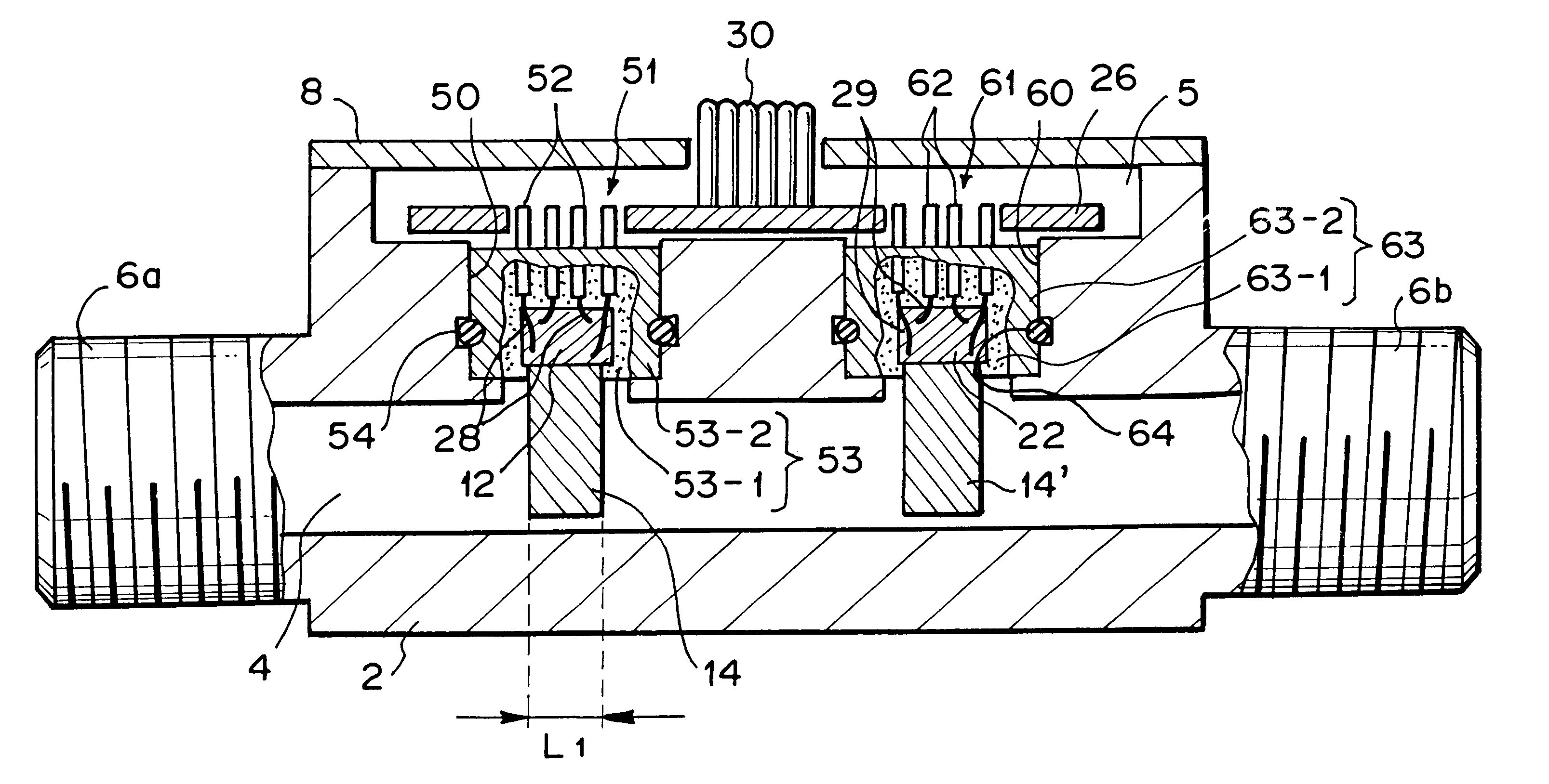
  • Flow rate sensor, temperature sensor and flow rate detecting apparatus
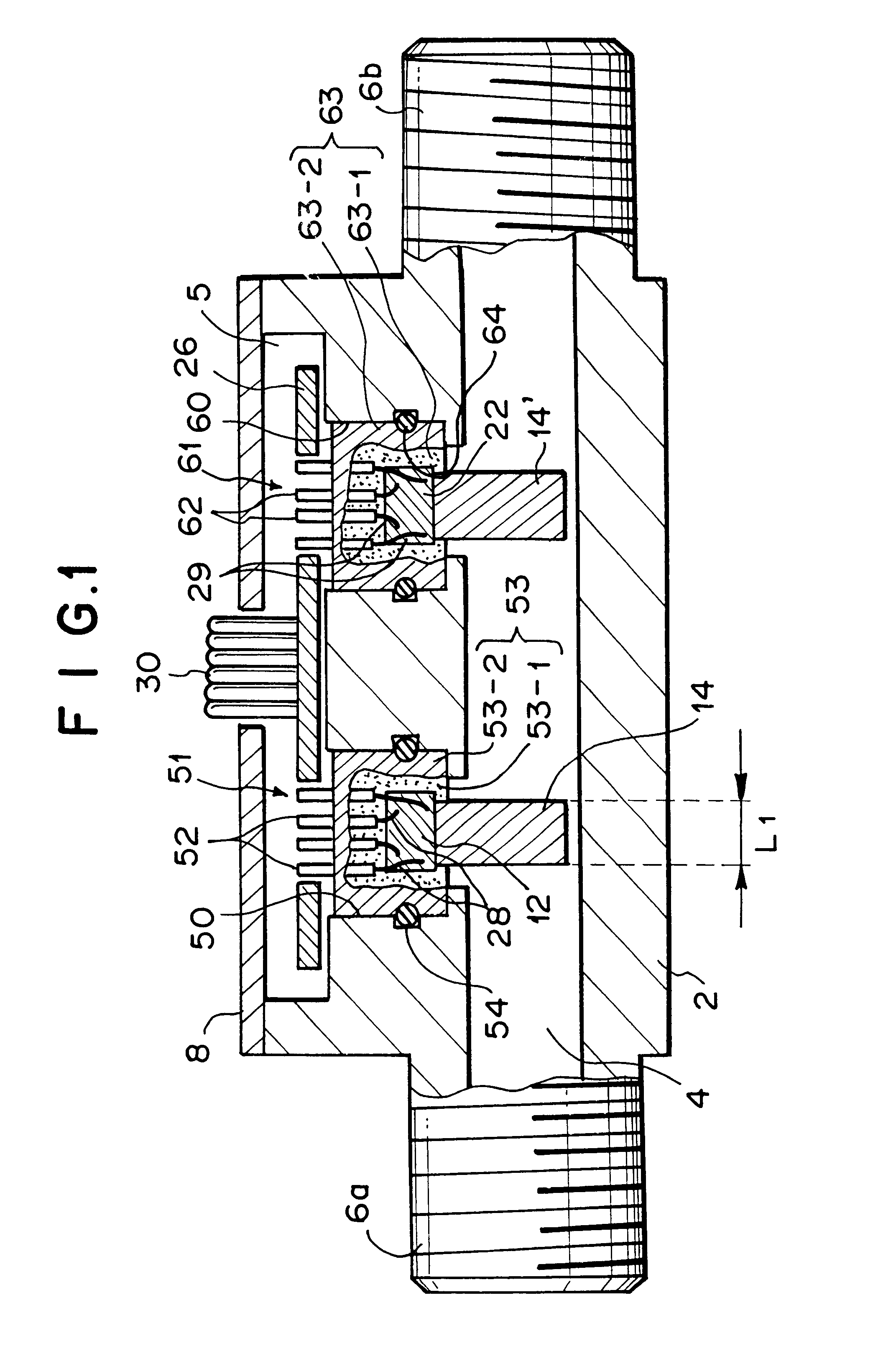
  • Flow rate sensor, temperature sensor and flow rate detecting apparatus
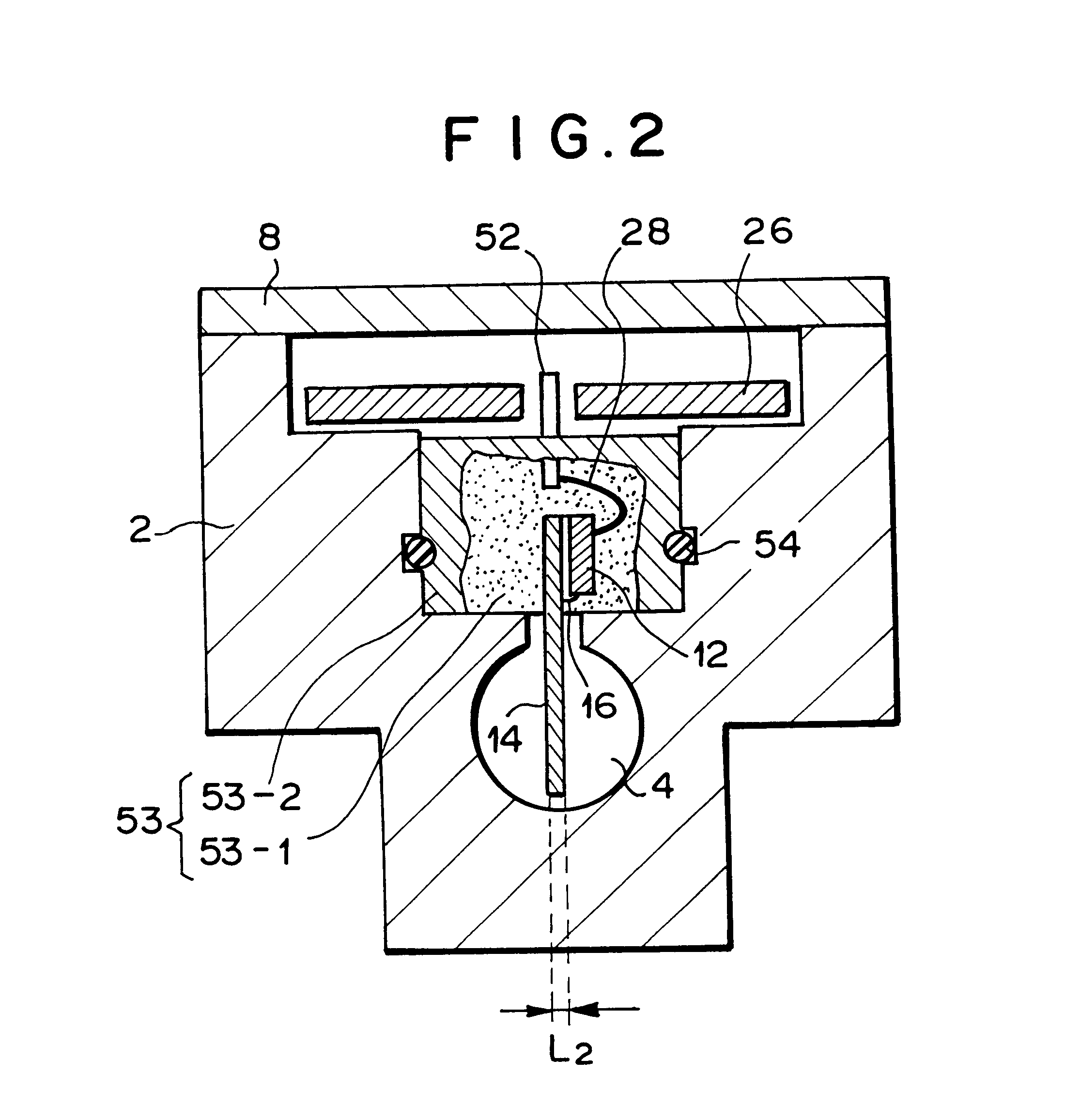
  • Flow rate sensor, temperature sensor and flow rate detecting apparatus

Examples


example

[EXAMPLE]

A flow rate detecting apparatus having the same construction as the flow rate detecting apparatus 451 described above was constructed by using the flow rate sensor 401 shown in FIGS. 22 and 23, and the flow rate was measured by using the flow rate detecting apparatus thus constructed.

Kerosene was used as fluid to be measured, and a predetermined amount of kerosene was put into the flow passage pipe 453. The amount of kerosene was increased or reduced to a predetermined amount at a time, and the flow rate was continuously measured. Thereafter, the variation of the output variation rate with time lapse from the switch time of the flow rate was determined.

The variation of the output variation rate with time lapse from a time point at which the flow rate was switched from 20 cc / minute to 80 cc / minute is indicated by reference character (A) in FIG. 30. Further, the variation of the output variation rate with time lapse from a time point at which the flow rate was switched from 8...


PUM


Abstract

A flow rate sensor for performing a flow rate detection of fluid with high accuracy without suffering adverse effect of the environmental temperature condition even when the fluid is viscous fluid having relatively high viscosity or the flow rate is relatively small is provided. The flow rate sensor includes a flow rate detector having a heating function and a temperature sensing function, and a pipe line for fluid to be detected which is formed so that heat from the flow rate detector is transferred to and absorbed by the fluid. The temperature sensing which is affected by a heat absorption effect of the fluid due to the heat is executed in the flow rate detector, and the flow rate of the fluid in the pipe line is detected on the basis of the temperature sensing result. Unit retaining portions formed on a casing in which the pipe line is formed, the unit retaining portions being disposed adjacent to the pipe line. A flow rate detecting unit comprising the flow rate detector is retained by the unit retaining portion, and a temperature detecting unit comprising a fluid temperature detector is retained by the unit retaining portion.

Description

(1) Field of the InventionThe present invention belongs to a fluid flow rate detection technology, and particularly relates to a flow rate sensor and flow rate detecting apparatus for detecting the flow rate of fluid flowing in a pipe line, and to a temperature sensor for detecting temperature of fluid when detecting the flow rate thereof. The flow rate sensor of the present invention is suitably used to accurately measure the flow rate of fluid under various temperature conditions and to make it easy to fabricate the flow rate sensor.Further, the present invention particularly intends to improve the measurement accuracy of the flow rate sensor, flow rate detecting apparatus and temperature sensor.(2) Description of Related ArtVarious types of sensors have been hitherto used as a flow rate sensor (or flow velocity sensor) for measuring the flow rate (or flow velocity) of various fluid, particularly liquid, and a so-called thermal (particularly indirectly heated type) flow rate senso...

Claims


Application Information

Patent Timeline
IPC IPC(8): G01F1/699G01F1/69G01F1/684G01F1/696G01F1/68G01F1/692
CPCG01F1/68G01F1/69G01F1/692G01F1/699
Inventor YAMAGISHI, KIYOSHIKAWANISHI, TOSHIAKITOMONARI, KENJIINOUE, SHINICHIKOIKE, ATSUSHI
Owner MITSUI MINING & SMELTING CO LTD
Learn More