Feeding heads for fastening machines

a technology of fastening machine and feeding head, which is applied in the direction of nail dispenser, paper/cardboard container, manufacturing tool, etc., can solve the problems of limited access to fastening operation, extremely limited, and limited parts

Inactive Publication Date: 2003-07-15
JPMORGAN CHASE BANK NA
View PDF6 Cites 87 Cited by
  • Summary
  • Abstract
  • Description
  • Claims
  • Application Information

AI Technical Summary

Benefits of technology

a gas control means is operative to effect or establish a gas pressure in the fastener passage which is operative to maintain a fastener therein in contact with, or in proper alignment or orientation to, the drive means as the drive means is advanced in the fastener guide passage. In order to effect the desired outcome the cross sectional dimension of the fastener passage is ideally closely fitted to the radial dimension of the fastener

Problems solved by technology

While the fastening machines or tools disclosed in the above documents have found commercial acceptance, customers continue to propose new applications for fasteners, fastening diverse ranges of workpieces together, and particularly where access for the fastening operation is restricted, and sometimes extremely limited.
The need to provide fastener aligning, centralising, and anti-tumbling features in the fastening head

Method used


Image

  • Feeding heads for fastening machines
  • Feeding heads for fastening machines
  • Feeding heads for fastening machines

Examples


Embodiment Construction

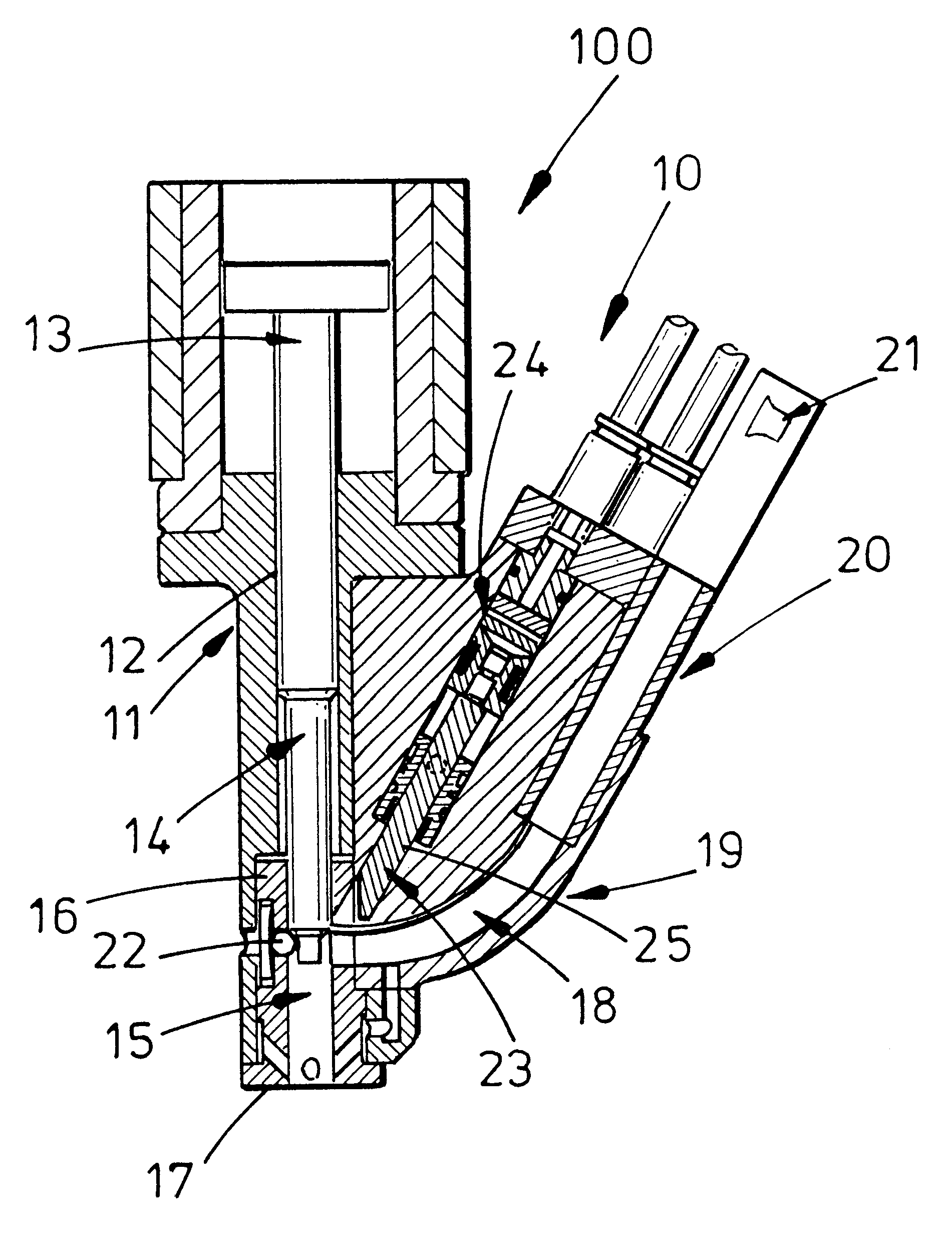
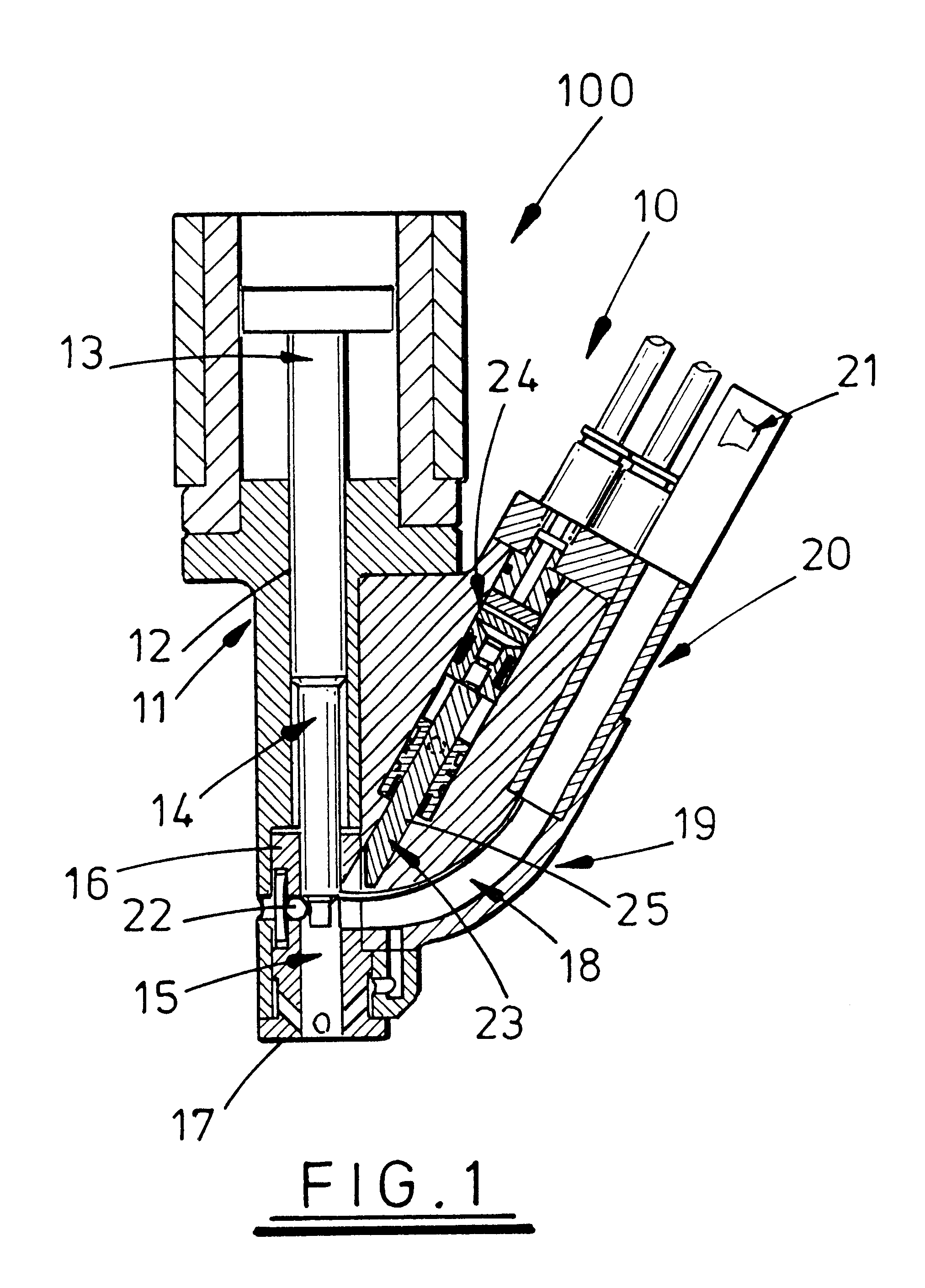
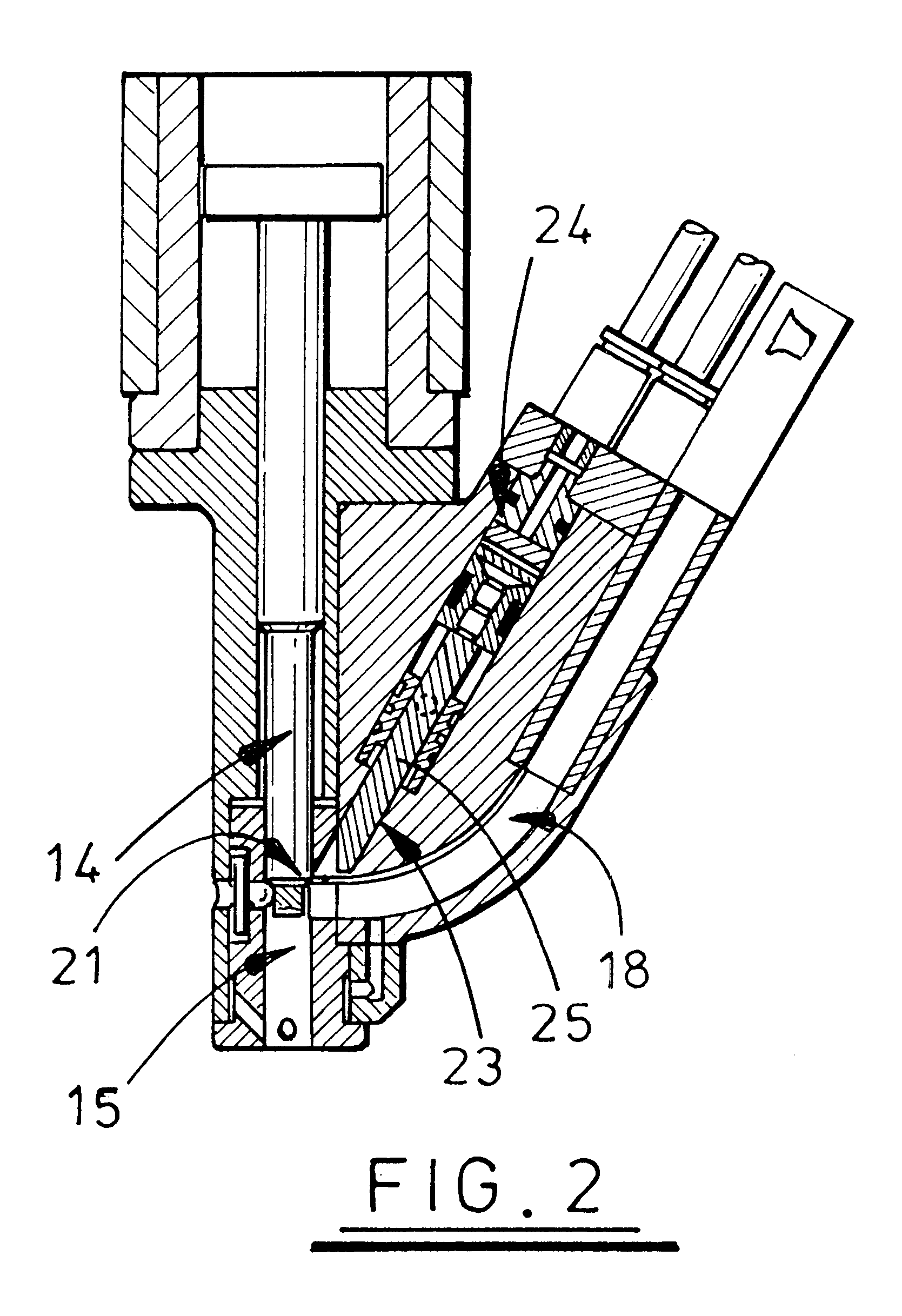
Referring to FIGS. 1 to 3, a fastener feeding head 10 for a fastening machine 100 may have a guide means which, in this embodiment, includes bush 11 with a fastener passage or bore 12 (hereinafter referred to as a bore for convenience) in which may be coaxially mounted a drive means such as plunger 13 (which will vary in character depending on what style of fastener is used, which, in turn, decides what action is to be performed by the drive means, hereinafter referred to as a plunger for convenience) which can be associated, as shown, with a fastener engagement means such as punch 14 (which will vary depending on what style of fastener it is to engage with but is conveniently referred to as a punch hereinafter) located or fitted at its forward end. The plunger is mounted for reciprocal advance and retractive movement in the bush 11. A fastener passage 15 is provided in the bush leading to a front end or nose portion 16 of the guide bush 11 and up to the front face or nose 17. The f...


PUM

PropertyMeasurementUnit
Pressureaaaaaaaaaa
Shapeaaaaaaaaaa

Abstract

A fastener feeding head (10) has fasteners (21, 121, 221) supplied to a fastener passage (15, 115, 215) aligned with a fastener engagement means (14, 114, 214) driven down the fastener passage by a drive means (13) to engage the fastener with workpieces (31, 131, 231). A charge of compressed gas is used to hold the fastener (21, 121, 221) against its engagement means (14, 114, 214).

Description

1. Field of the InventionThis Invention relates to automatic fastening machines or tools, and, in particular, to the fastener delivery head for such automatic fastening machines or tools.2. Prior ArtPrior patent specifications, PCT / AU92 / 00621(WO 93 / 09918) and PCT / AU94 / 00013(WO 94 / 15736) by the present applicant both disclose automatic fastening machines or tools wherein the fastening head thereof operates with rivets and other types of fasteners, fed thereto in alignment with a punch or engagement tool therefor, and supporting the rivets or other fastener as the punch or engagement tool advances the rivet or other fastener towards a workpiece (and typically an upsetting die in the case of rivets).While the fastening machines or tools disclosed in the above documents have found commercial acceptance, customers continue to propose new applications for fasteners, fastening diverse ranges of workpieces together, and particularly where access for the fastening operation is restricted, an...

Claims


Application Information

Patent Timeline
IPC IPC(8): B25B23/04B25B23/02B21J15/00B21J15/32B23P19/00B21J15/02B25B23/08B21J15/30B21J15/34
CPCB21J15/025B21J15/32B21J15/323B23P19/001B25B23/04B25B23/045
Inventor GOSTYLLA, WOJCIECHBLACKET, STUART EDMUND
Owner JPMORGAN CHASE BANK NA
Why Eureka
Try Eureka