Power inside corner planer and method of use

a power inside corner and power planer technology, applied in hand planes, roofs, building materials handling, etc., can solve the problems of buckling or warping of studs, and the conventional electric power planer is not very useful on an inside corner

Inactive Publication Date: 2003-09-02
SMITH BILLY JOE
View PDF2 Cites 10 Cited by
  • Summary
  • Abstract
  • Description
  • Claims
  • Application Information

AI Technical Summary

Benefits of technology

FIG. 1 is a bottom plan view of

Problems solved by technology

The carpenters try to make the planes of the walls flat as they go but sometimes they make a mistake and insert bent studs

Method used


Image

  • Power inside corner planer and method of use
  • Power inside corner planer and method of use
  • Power inside corner planer and method of use

Examples


second embodiment

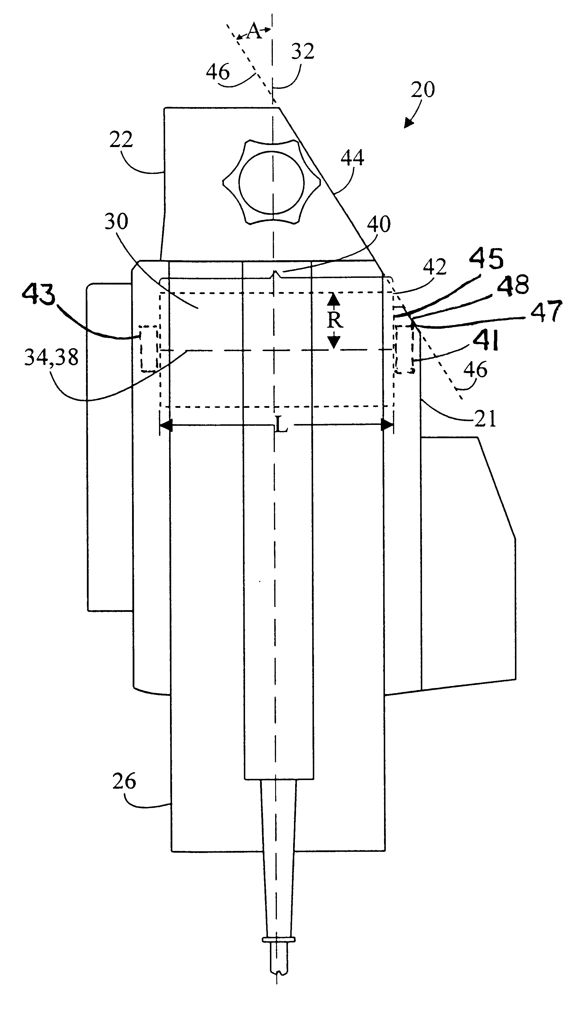
FIGS. 6 and 11 show that a power inside corner planer can be constructed with an angled side on either the right or left. Because of the throw of the chips away from the planer, it is generally more desirable to have the chips thrown down away from the operator instead of up where they can ricochet around and the smaller particles can float around. This means that the preferred method for using an inside corner planer is to push it up in the corner. Since half of the sides of corners to be planed are on the right side and half of the sides are on the left side, inside comer planers of both the first and second embodiment would be useful to a carpenter.

FIGS. 12 and 13 are bottom plan and top plan views, respectively, of a third embodiment of the planer of the present invention, generally designated as 120. The third embodiment combines the features of both the first and second embodiments of FIGS. 6 and 11. It has angled sides on both sides so that it may be pushed up in an inner com...

third embodiment

In the third embodiment, cutter assembly 130 is separated into two cutters, right cutter 133 and left cutter 135, by a central drive belt 131. The requirement for a central drive belt 131 will leave a small unplaned area in the middle. This unplaned area is somewhat minimized by the fact that the cutter 130 operates at an angle so that the unplaned width is always less than the width of the belt. Also, cutter assembly 130 can be constructed so that each of its left and right cutters 133 and 135 are wide enough to independently complete a corner planing job by itself.

FIG. 14 is a reduced top plan elevation view of the third embodiment planer 120 planing a surface 604 adjacent a left interfering structure 606, and FIG. 15 is a reduced top plan view of the third embodiment planer 120 planing a surface 600 adjacent right interfering structure 602. The advantage of planer 120 is that it may plane close to two opposite interfering structures 602 and 606 while only being moved in an upward...


PUM


Abstract

An electric inside corner planer (20) with a cylindrical cutter assembly (30) has a housing (21) and front shoe (22) constructed with a side angled along a line (46) determined by the front outside of the cutter (30) and the front outside of the bearing (41) holding the cutter. The angled side of the planer puts the cutter assembly as close as possible to the interfering structure in the corner. Right angled (20), left angled (70), and combined right and left angled (120) planer embodiments are shown.

Description

The present invention pertains generally to electric power planers, and more particularly to an inside corner power planer which permits the user to plane areas close to interfering structures such as an adjacent perpendicular wall.As a part of the construction of a wood frame house, one stage is the erection of stud walls and other wood framing. The carpenters try to make the planes of the walls flat as they go but sometimes they make a mistake and insert bent studs or studs warp later due to moisture. Prior to installing sheet rock panels on a wall, a crew uses a level to make sure the outer surfaces of the studs in the wall are all in the same plane. Any studs that are out of the plane of the wall are planed off with an electric planer if they are too high or built up using thin wood strips if they are too low until the wall is perfectly flat. A conventional electric power planer can be used for most of the work including the leveling of outside corners. However, a conventional e...

Claims


Application Information

Patent Timeline
IPC IPC(8): B27C1/10B27C1/00E04F21/00
CPCB27C1/10E04F21/00
Inventor MANN, CHRISTOPHER L.
Owner SMITH BILLY JOE
Why Eureka
Try Eureka