Grinding jig

a technology of grinding jigs and jigs, which is applied in the direction of knives, hand equipment, applications, etc., can solve the problem of unstable grinding

Inactive Publication Date: 2003-09-23
TORMEK
View PDF6 Cites 20 Cited by
  • Summary
  • Abstract
  • Description
  • Claims
  • Application Information

AI Technical Summary

Problems solved by technology

If the shank surface is not straight, but convex, the shank rides in the middle of the jig under the screw, which means that the clamping is not stable.

Method used


Image

  • Grinding jig
  • Grinding jig
  • Grinding jig

Examples


Embodiment Construction

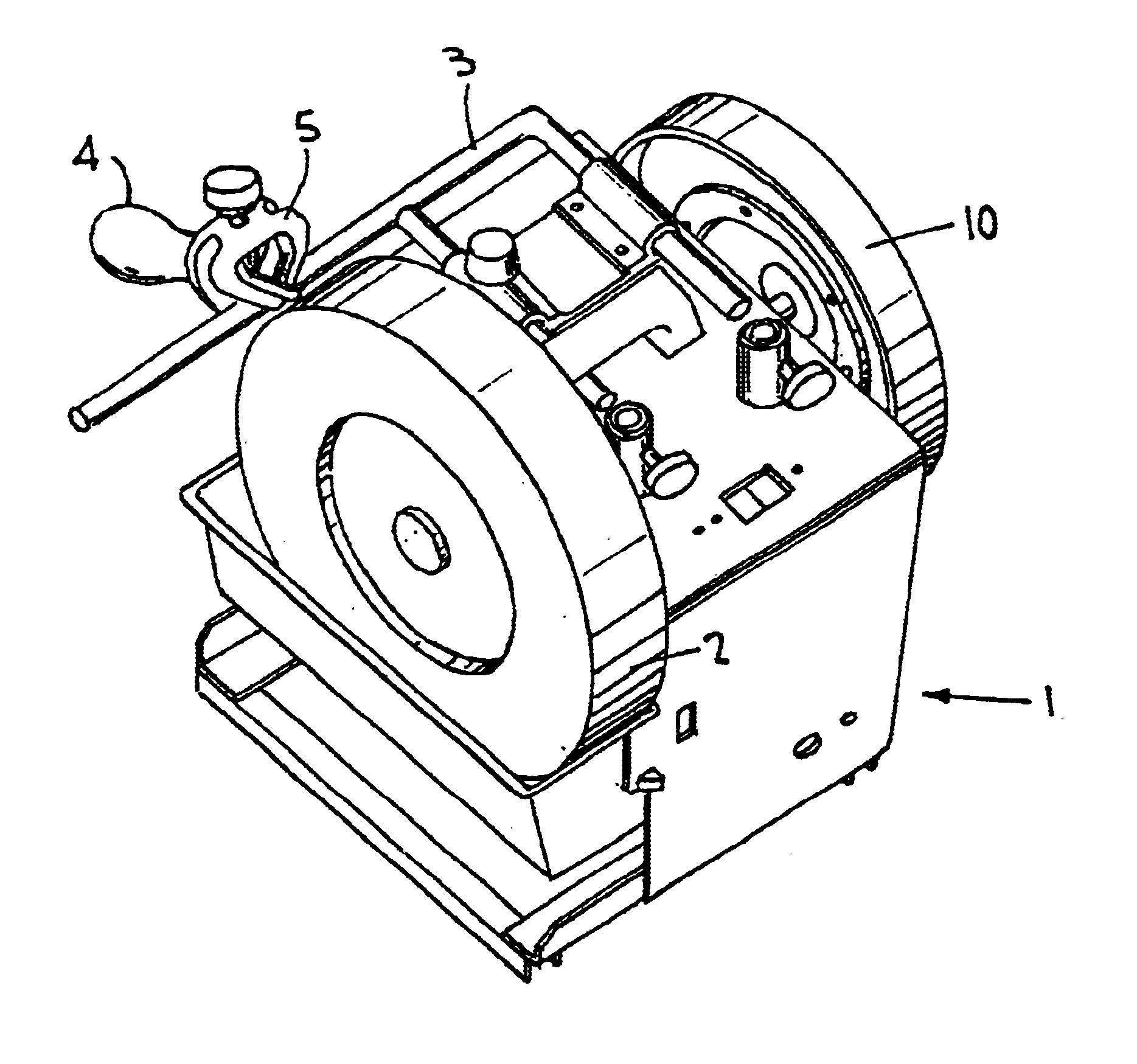
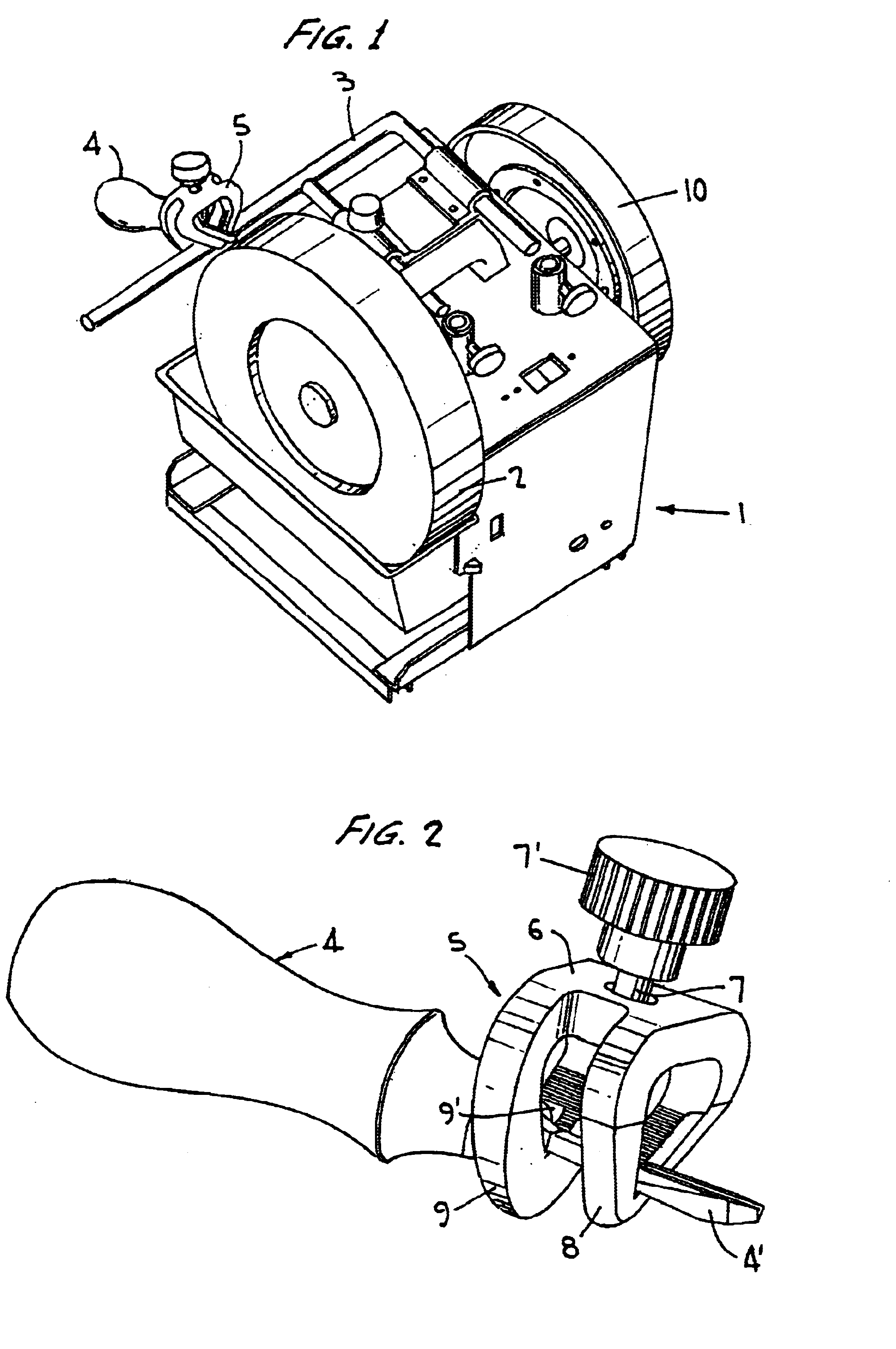
A conventional grinding machine 1 is shown in FIG. 1. The machine is provided with a grindstone 2 driven by an electric motor in the machine. In the present case the grindstone 2 is driven at a comparatively low speed, but it may alternatively be driven at a high speed. The machine 1 is provided with a cylindrical support bar 3. The purpose of the support bar 3 is--as indicated in FIG. 1--to serve as a guiding means for an edge tool 4 to be sharpened by the grindstone 2.

For the general purpose of assisting the operator to hold the tool 4 correctly in relation to the grindstone 2 and on the support bar 3, a grinding jig 5 may be used.

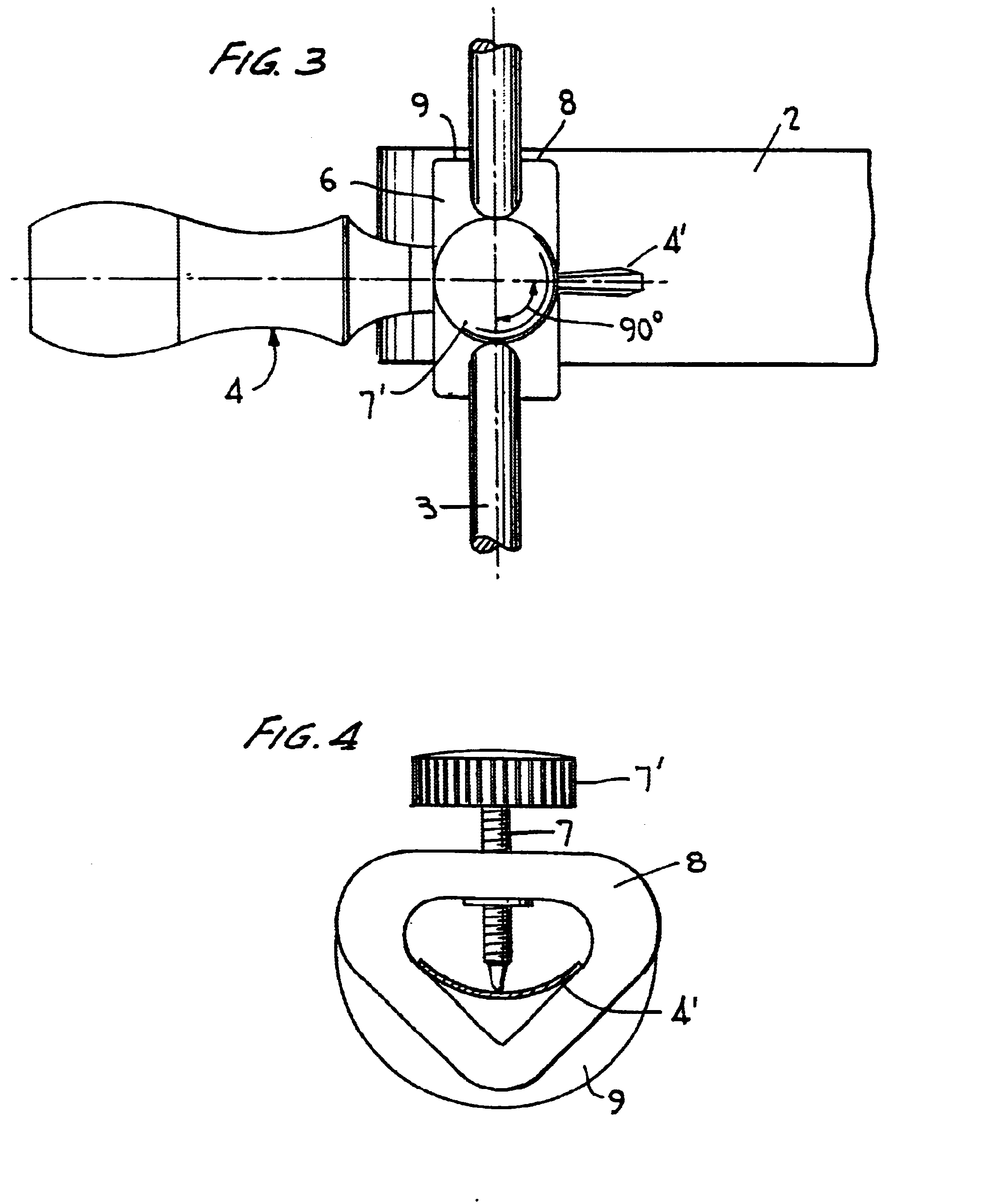
When grinding an edge tool 4 on the grindstone 2 it is important that the tool is held at a constant angle against the grindstone, so that the tool edge gets a single bevel only and not any extra or unwanted bevels. The tool also has to be held steadily sideways, so that a clean and sharp edge is obtained.

A grinding jig accordingly has the purpose of ass...


PUM

PropertyMeasurementUnit
edge angleaaaaaaaaaa
lengthaaaaaaaaaa
lengthaaaaaaaaaa

Abstract

A grinding jig (5) is to be attached on an edge tool (4) to be ground on a rotating grindstone (2) in a grinding machine (1), having a support means (3) in the vicinity of the grindstone. The jig is split by having a base portion (6) and two parallel open yokes (8, 9) extending therefrom. A screw (7) for clamping the tool (4) against the bottoms of the yokes is provided in the base portion between the two yokes.

Description

The present invention relates to a grinding jig for attachment on an edge tool to be ground on a rotating grindstone in a grinding machine, having a support means in the vicinity of the grindstone.Such a grinding jig is used for holding the tool at a constant angle towards the grindstone, so that the tool edge gets a single bevel without any extra and non-desired bevels, but also for holding it steadily sideways for obtaining a clean and sharp edge.A conventional grinding jig may be an open yoke with a certain width. The tool is to be inserted in the yoke and is clamped therein by a screw. At grinding, the rear side of the yoke or the side of the yoke facing from the grindstone and the tool shank is applied against the support means, usually in the form of a cylindrical support bar.The opening in a jig suitable for grinding curved gouges may preferably have a triangular shape, so that the tool shank is clamped by the screw against the V-shaped bottom of the jig.By the geometry at gr...

Claims


Application Information

Patent Timeline
Patent Type & Authority Patents(United States)
IPC IPC(8): B24B3/38B24B3/00B24B41/06
CPCB24B3/38B24B41/066
Inventor JANSSON, TORGNY
Owner TORMEK
Why Eureka
Try Eureka