Window for installation in a roof and a mounting bracket for use in the installation of roof penetrating structures

a technology for installing windows and roofs, which is applied to roof coverings, structural elements, building components, etc., can solve problems such as damage to brackets or other objects, and achieve the effect of improving installation conditions

Inactive Publication Date: 2003-10-07
VKR HLDG AS
View PDF13 Cites 49 Cited by
  • Summary
  • Abstract
  • Description
  • Claims
  • Application Information

AI Technical Summary

Benefits of technology

It is an object of the invention to provide a window of the kind mentioned by way of introduction, in which the installation conditions are improved even further and the requirements to tools and fastening means such as screws and nails which have to be carried along by the installer are minimized.

Problems solved by technology

Due to the fact that adjustment takes places at the installation site it is not considered convenient to pre-mount such mounting brackets, the more so as the second leg of the bracket would be protruding from the plane of the window frame, thereby necessitating a larger packaging and there is also a risk of damaging the brackets or of the bracket causing damage to other objects.

Method used


Image

  • Window for installation in a roof and a mounting bracket for use in the installation of roof penetrating structures
  • Window for installation in a roof and a mounting bracket for use in the installation of roof penetrating structures
  • Window for installation in a roof and a mounting bracket for use in the installation of roof penetrating structures

Examples


Embodiment Construction

.

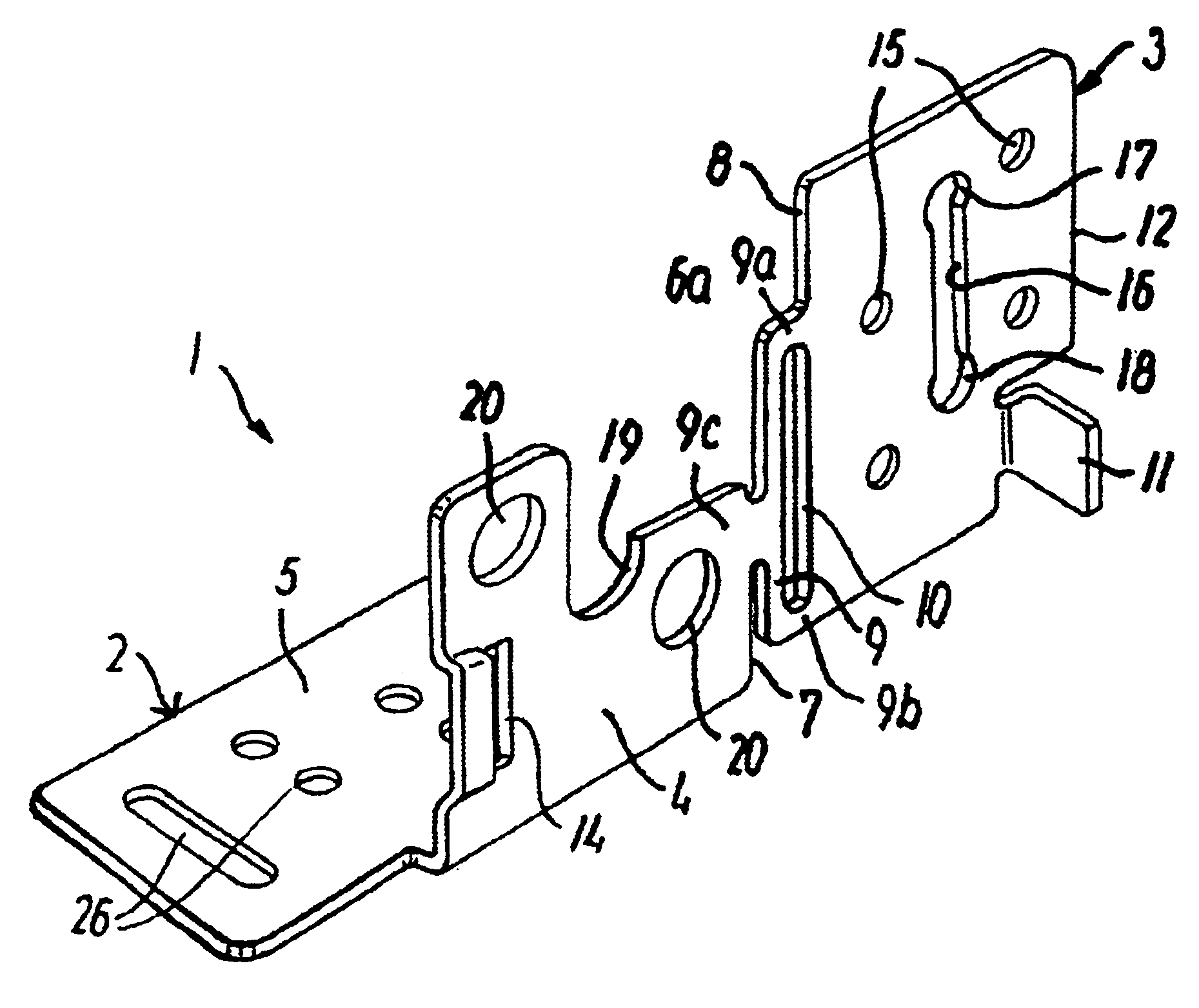
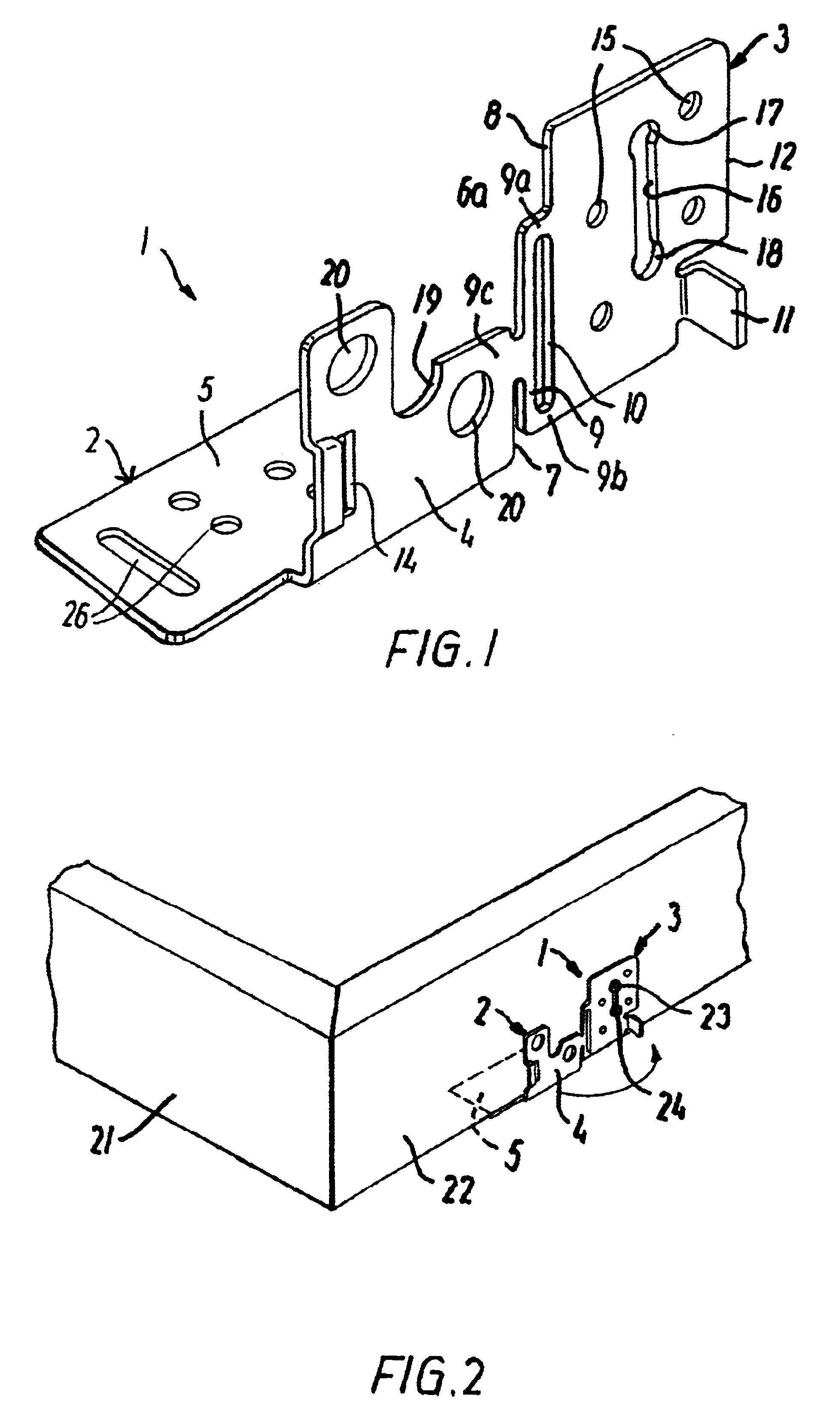
FIG. 1 illustrates a mounting bracket generally designated 1 and (comprising an angular bracket member 2 and a substantially plate-shaped base member 3. The angular bracket member 2 has a first leg 4 and a second leg 5 extending at substantially right angles from the lower edge of the first leg 4 and in integral connection therewith. The angular bracket member 2 is connected with the base member 3 by means of a connecting portion 6 extending between respective first side edges 7 and 8 of the first leg 4 of the angular bracket member 2 and the base member 3, respectively. The connecting portion 6 comprises a bridge 9 connected integrally at each end 9a, 9b with the first side edge 8 of the base member 3, and at a central portion 9c with the first side edge 7 of the first leg 4 of the angular bracket member 2, thus forming a gap 10 between the bridge 9 and the first edge 8 of the base member 3.

The mounting bracket 1 is furthermore provided with locking means for locking the angular b...


PUM


Abstract

A window for installation in a roof includes a window frame with frame pieces and mounting brackets. Each bracket includes an angular bracket member with first and second legs connected integrally with each other, and a substantially plate-shaped base member having an opening for receiving fasteners and is connected with the outer side wall of the frame piece. The angular bracket member is connected with the base member such that, in a transportation position of the window, the second leg of the angular bracket member protrudes inwards in relation to the base member, and, in an installation position, the second leg protrudes outwards. Locking mechanism locks the first leg relative to the base member in the installation position, and adjusting mechanism adjusts the position of the angular bracket member in at least a transverse direction perpendicular to the longitudinal direction of the frame piece of the window frame.

Description

BACKGROUND OF THE INVENTION.The present invention relates to a window for installation in a roof of the type having an inclined roof surface and an underlying supporting structure, said window comprising a window frame with frame pieces, each extending in a longitudinal direction and having an outer side wall defining a plane substantially perpendicular to the roof surface, and a plurality of mounting brackets; wherein each mounting bracket comprises: an angular bracket member having a first and a second leg connected integrally with each other, and a substantially plate-shaped base member having at least one opening for receiving fastening means and being connected with the outer side wall of the window frame piece, said base member defining a plane which is parallel to said outer side wall plane, the angular bracket member being connected with the base member in such a way that in a transportation position of the window the second leg of said angular bracket member protrudes inwar...

Claims


Application Information

Patent Timeline
Patent Type & Authority Patents(United States)
IPC IPC(8): E04D13/03E06B1/56
CPCE04D13/031
Inventor B.O SLASHED.RRESEN, BJARNELINDGREN, CLAESNISSEN-SCHMIDT, LARS J.O SLASHED.RNQUARLES, WAYNE
Owner VKR HLDG AS
Why Eureka
Try Eureka