Multiple chamber self-inflatable body

a self-inflating, multi-chamber technology, applied in the direction of fluid mattresses, envelopes/bags making machinery, paper/cardboard containers, etc., can solve the problems of pad failure to perform as intended, loss of air in the enclosure, collapse of the enclosure,

Inactive Publication Date: 2003-11-25
CASCADE DESIGNS INC
View PDF10 Cites 52 Cited by
  • Summary
  • Abstract
  • Description
  • Claims
  • Application Information

AI Technical Summary

Benefits of technology

The invention is directed to a multiple chamber inflatable body that combines both a self-inflating chamber or compartment and a second chamber or compartment. The second chamber may be constructed to removably receive a resilient member, to permanently retain a resilient member, or to exhibit self-inflating properties. By this invention in its various embodiments, benefits inherent in a self-inflating style ground pad and a conventional self-supporting pad can be attained.
By incorporating a user operable valve at the orifice that is in fluid communication with the first chamber and the environment, a user can control the state of the first chamber. Thus, when the valve is opened, air from the environment is drawn into the first chamber by the partial vacuum created by the expanding foam until equilibrium is reached, whereafter the valve is closed. When the valve is again opened and the first chamber compressed, air is expelled until the valve is again closed, whereafter the compressed state of the first chamber is maintained.

Problems solved by technology

Occasionally during use, such pads are punctured, which results in the loss of air in and collapse of the enclosure.
Because the open cell foam is selected for its appropriateness as a tensile element, it does not perform well when in compression.
As a consequence, the pad will fail to perform as intended until the enclosure is again sealed from the environment.

Method used


Image

  • Multiple chamber self-inflatable body
  • Multiple chamber self-inflatable body
  • Multiple chamber self-inflatable body

Examples


Embodiment Construction

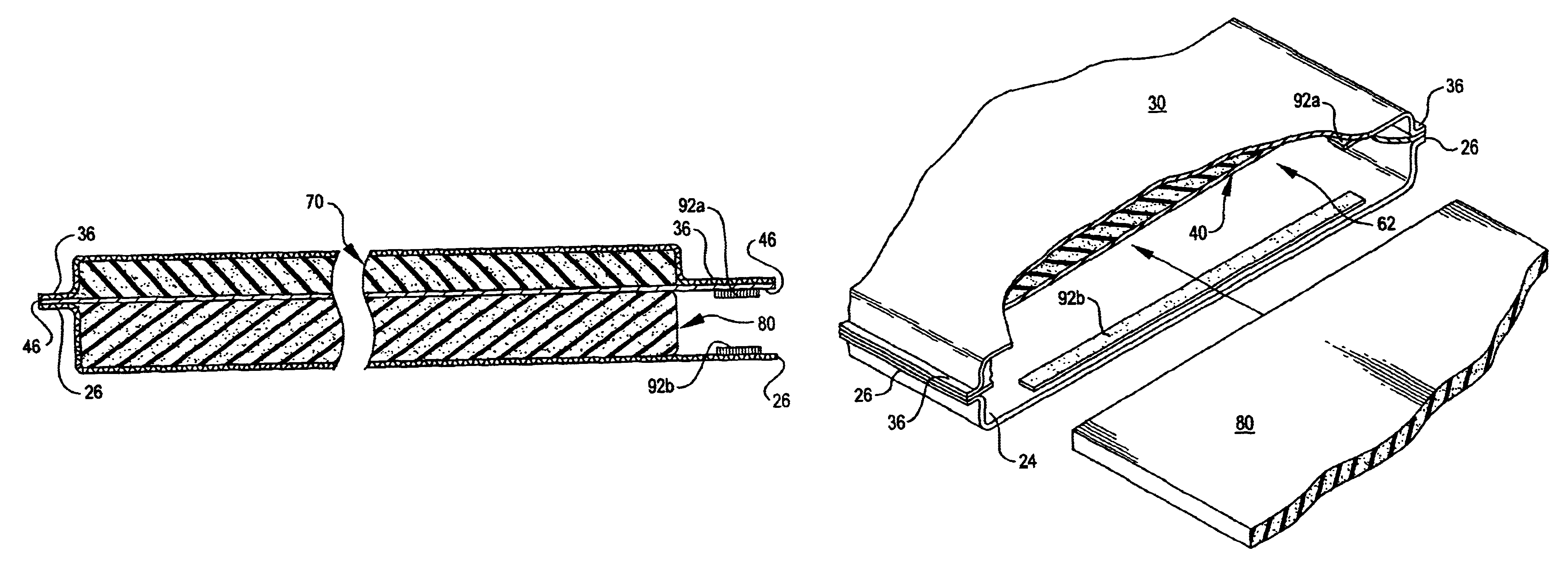
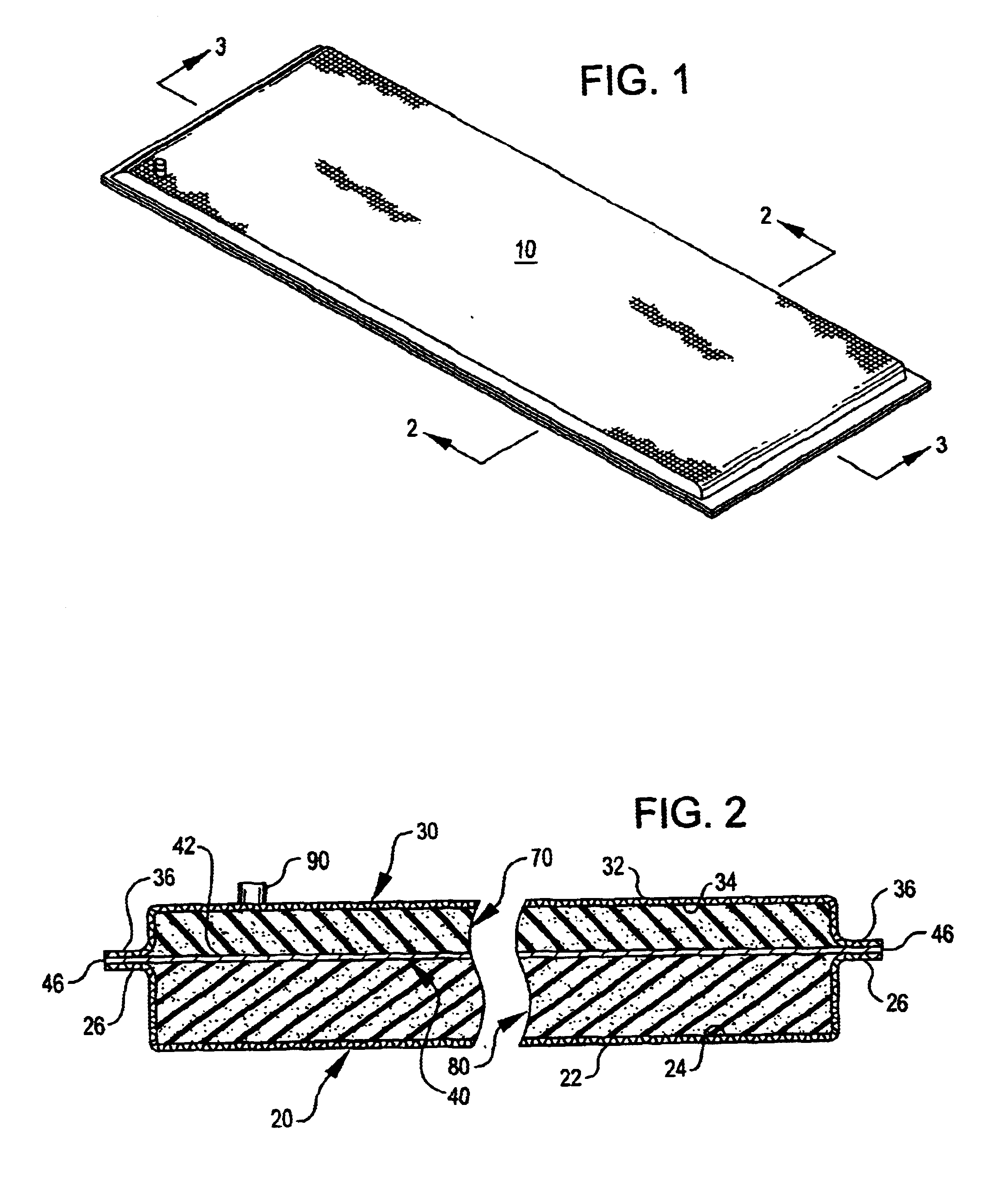
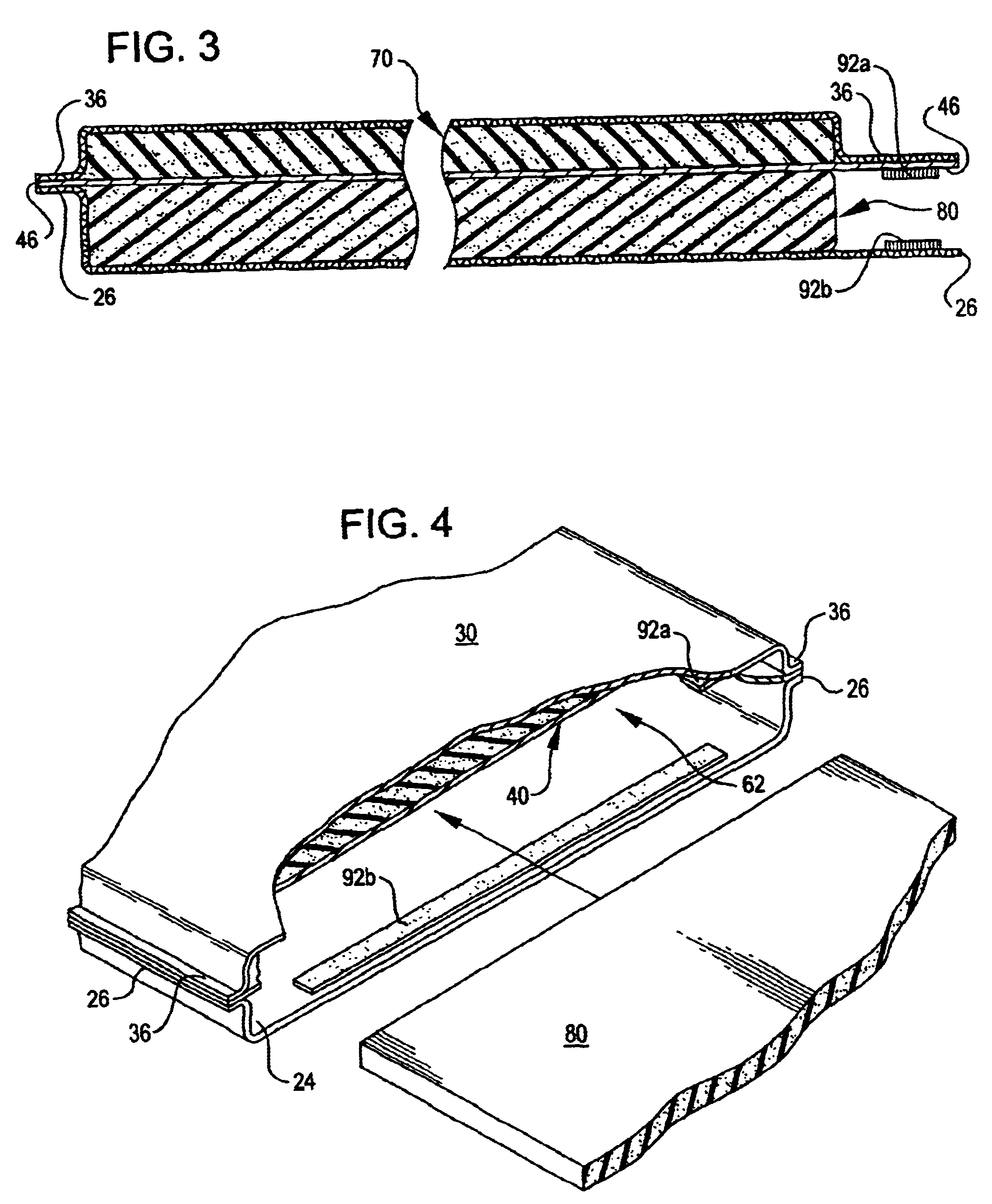
Turning then to the several drawings wherein like numerals indicate like parts, and more particularly to FIGS. 1-3 and 5, the general attributes and construction of combination pad 10 are shown. Pad 10 comprises bottom panel 20, top panel 30, and intermediate panel 40, which are selectively attached to one another in order to form two chambers. One chamber is preferably a fluid impervious chamber sealed from the external environment and includes self expanding and maintaining features, while the other chamber is intended to selectively receive a removable resilient member.

Again returning to the referenced figures, bottom panel 20 includes outside surface 22, inside surface 24, and periphery 26. Similarly, top panel 30 includes outside surface 32, inside surface 34, and periphery 36. Finally, intermediate panel 40 includes upper surface 42, lower surface 44, and periphery 46. Shown disposed in first or upper chamber 50 is resilient member 70; shown disposed in second or lower chamber...


PUM

PropertyMeasurementUnit
flexibleaaaaaaaaaa
resilientaaaaaaaaaa
thermal reflectiveaaaaaaaaaa

Abstract

A multiple chamber self-inflating pad having a fluid impervious first chamber defined by a first flexible panel and an intermediate panel in which a first resilient member is disposed and to which the resilient member is bonded. An orifice is provided to control inflation or deflation of the first chamber. A second flexible panel is selectively bonded to the intermediate flexible panel preferably to form a gap or pocket into which a second resilient member may be removably disposed. Preferably, the first resilient member is an open cell foam while the second is constructed from closed cell foam. Alternative embodiments include the creation of a fluid impervious second chamber either fluidly linked to the first chamber or to the environment, alternative resilient materials, inclusion of radiant barriers, and the like.

Description

BACKGROUNDSelf-inflating cushions or pads are well known. A leader in this field is Cascade Designs, Inc., maker of the THERM-A-REST.RTM. brand self-inflating mattress pad as well as numerous others based upon the same or similar technology. This technology uses a slab of open cell foam bonded between two flexible sheets of material that are in turn bonded to each other at the perimeter of the slab. The result of this construction yields a fluid impervious enclosure wherein the slab acts as a tensile element to resist uncontrolled shape deformation of the enclosure. In other words, the enclosure retains the shape of the slab when the enclosure is pressurized above atmospheric pressure since the bonded foam resists the tendency of the sheets to go non-planar.Occasionally during use, such pads are punctured, which results in the loss of air in and collapse of the enclosure. Because the open cell foam is selected for its appropriateness as a tensile element, it does not perform well wh...

Claims


Application Information

Patent Timeline
Patent Type & Authority Patents(United States)
IPC IPC(8): A47C27/14A47C27/18B32B5/32B32B5/22
CPCA47C27/084A47C27/088A47C27/15B32B5/32A47C27/18Y10T428/239Y10T428/13Y10T428/233
Inventor MARSON, JAMES E.
Owner CASCADE DESIGNS INC
Why Eureka
Try Eureka