
Plasma display panel and the manufacturing method thereof

a technology of display panel and plasma, which is applied in the manufacture of electrode systems, electric discharge tubes/lamps, gas exhaustion means, etc., can solve the problems of compromising the opening rate of the pdp, and affecting the operation of the pdp

Inactive Publication Date: 2003-12-30
AU OPTRONICS CORP
View PDF7 Cites 18 Cited by
  • Summary
  • Abstract
  • Description
  • Claims
  • Application Information

AI Technical Summary

Benefits of technology

Another object of the present invention is to provide the manufacturing method of the partition wall structure of the PDP, and defines the size of cut of the partition wall structure required by using simple procedures.

Problems solved by technology

Since the front substrate has an additional rib manufacturing process in the NEC structure, the cost is relatively high.
When assembling the front and the back substrates, the high aligning precision of the two substrates is strictly required; this deepens the difficulty of the manufacturing process.
Hence the opening rate of the PDP is compromised.

Method used


Image

  • Plasma display panel and the manufacturing method thereof
  • Plasma display panel and the manufacturing method thereof
  • Plasma display panel and the manufacturing method thereof

Examples


Embodiment Construction

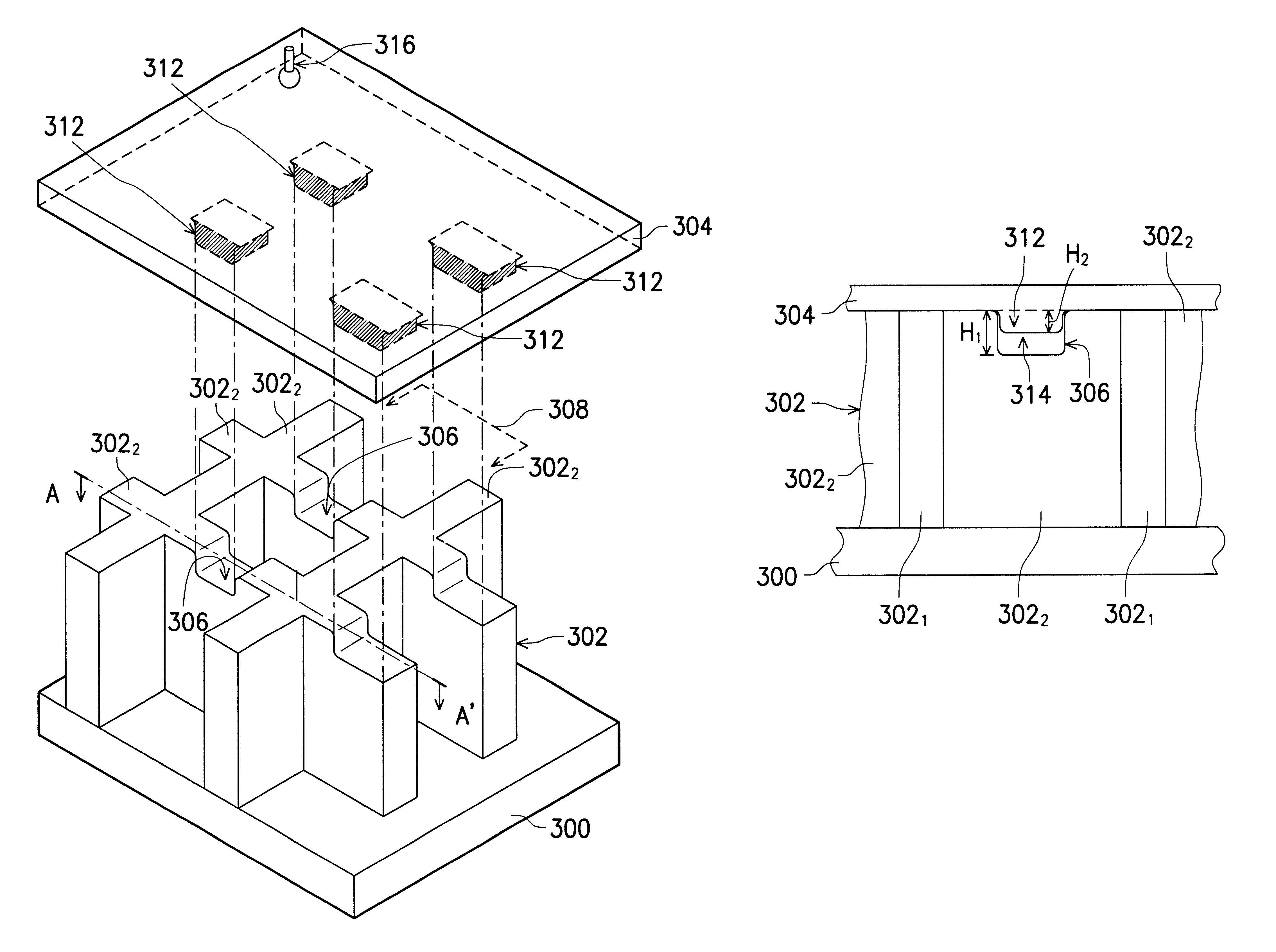
FIG. 3A shows the schematic diagram of the assembly of partial structure of the front and back substrates of PDP. FIG. 3B shows the cross-sectional view along A-A' after FIG. 3A is assembled.

Refer to FIGS. 3A and 3B, the plasma display panel disclosed by the present invention includes a first substrate 300 and a second substrate 304 parallel to the first substrate 300, thereby forming a discharging space between the first substrate 300 and the second substrate 304. A partition wall structure is formed on the first substrate and a plurality of column-shaped protrusions 312 on the second substrate 304, and an air-pump hole 316 formed on the second substrate.

The partition wall structure 302 on the first substrate includes a plurality of first stripe ribs 302.sub.1 and a plurality of second stripe ribs 302.sub.2, the plurality of first stripe ribs 302.sub.1 define the discharging space to become a plurality of row discharging space 308; each of the second stripe ribs 302.sub.2 crosses e...


PUM


Abstract

A plasma display panel and the manufacturing method thereof. Forming partition wall structures on the back substrate of the paste display panel and forming the column-shaped protrusions at the positions corresponding to the cuts on the rib on the front substrate of the plasma display panel. The manufacturing process is simple and the alignment of the front and back substrate is easy. In addition, the size of the opening of the rib and the size of the cut can be easily adjusted according to the needs of the application during the manufacturing process.

Description

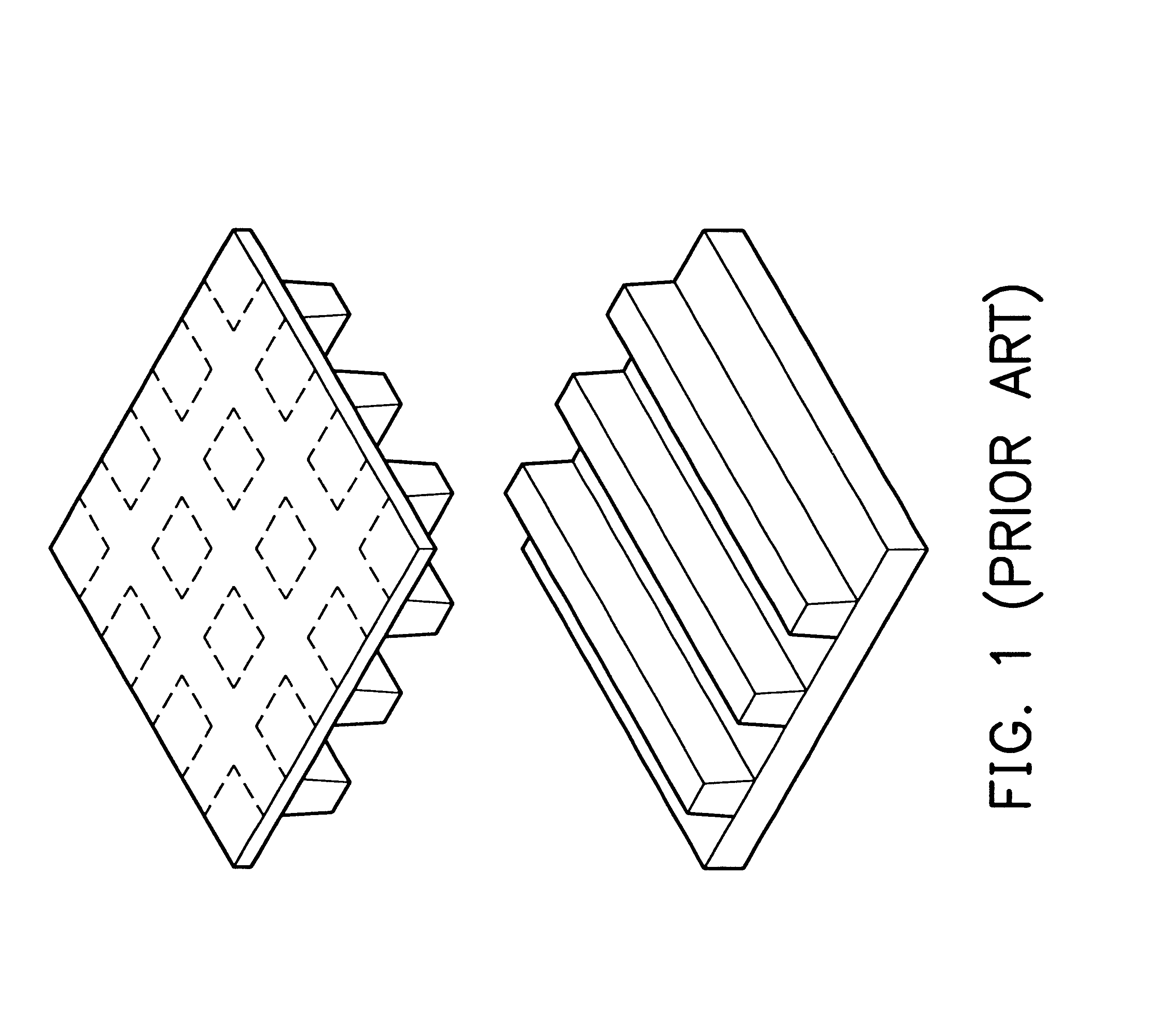
1. Field of the InventionThe present invention relates to a plasma display panel and the manufacturing method thereof, more particularly to the partition wall structure of the panel and the manufacturing method thereof.2. Description of the Prior ArtThe rib of the plasma display panel (referred to PDP in the following) commonly has a stripe-shaped structure. However, the grid-mesh rib structure is also used at present, for example, the one disclosed in the U.S. Pat. No. 5,701,056 by NEC. The structure disclosed by NEC forms stripe-shaped ribs on the back substrate of the PDP and forms grid-mesh-shaped ribs on the front substrate of the PDP, then assembles the front and back substrates, as shown in FIG. 1. The structure disclosed by NEC has the following four disadvantages:Since the front substrate has an additional rib manufacturing process in the NEC structure, the cost is relatively high.When assembling the front and the back substrates, the high aligning precision of the two subs...

Claims


Application Information

Patent Timeline
Patent Type & Authority Patents(United States)
IPC IPC(8): H01J17/02H01J17/49H01J17/16H01J11/10H01J11/12H01J11/36H01J11/54
CPCH01J9/242H01J11/10H01J11/12H01J11/54H01J11/36H01J2211/363H01J2211/36
Inventor LIN, CHU-SHANHO, BING-MINGCHIANG, TZU-PANG
Owner AU OPTRONICS CORP
Learn More