Flat spring clip for tool-less slide installation

a spring clip and tool-less technology, applied in the field of sliding assembly, can solve the problems of loose hardware, such as screws and bolts, that may be lost, and inconvenient to keep track

Inactive Publication Date: 2004-03-09
VALTRUS INNOVATIONS LTD
View PDF11 Cites 102 Cited by
  • Summary
  • Abstract
  • Description
  • Claims
  • Application Information

AI Technical Summary

Problems solved by technology

Also, certain techniques use loose hardware, such as screws and bolts, that may be lost and are inconvenient to keep track of.

Method used


Image

  • Flat spring clip for tool-less slide installation
  • Flat spring clip for tool-less slide installation
  • Flat spring clip for tool-less slide installation

Examples


Embodiment Construction

The following discussion of the embodiments of the invention directed to a slide assembly for slidably mounting a computer server unit to a rack is merely exemplary in nature, and is in no way intended to limit the invention or its applications or uses.

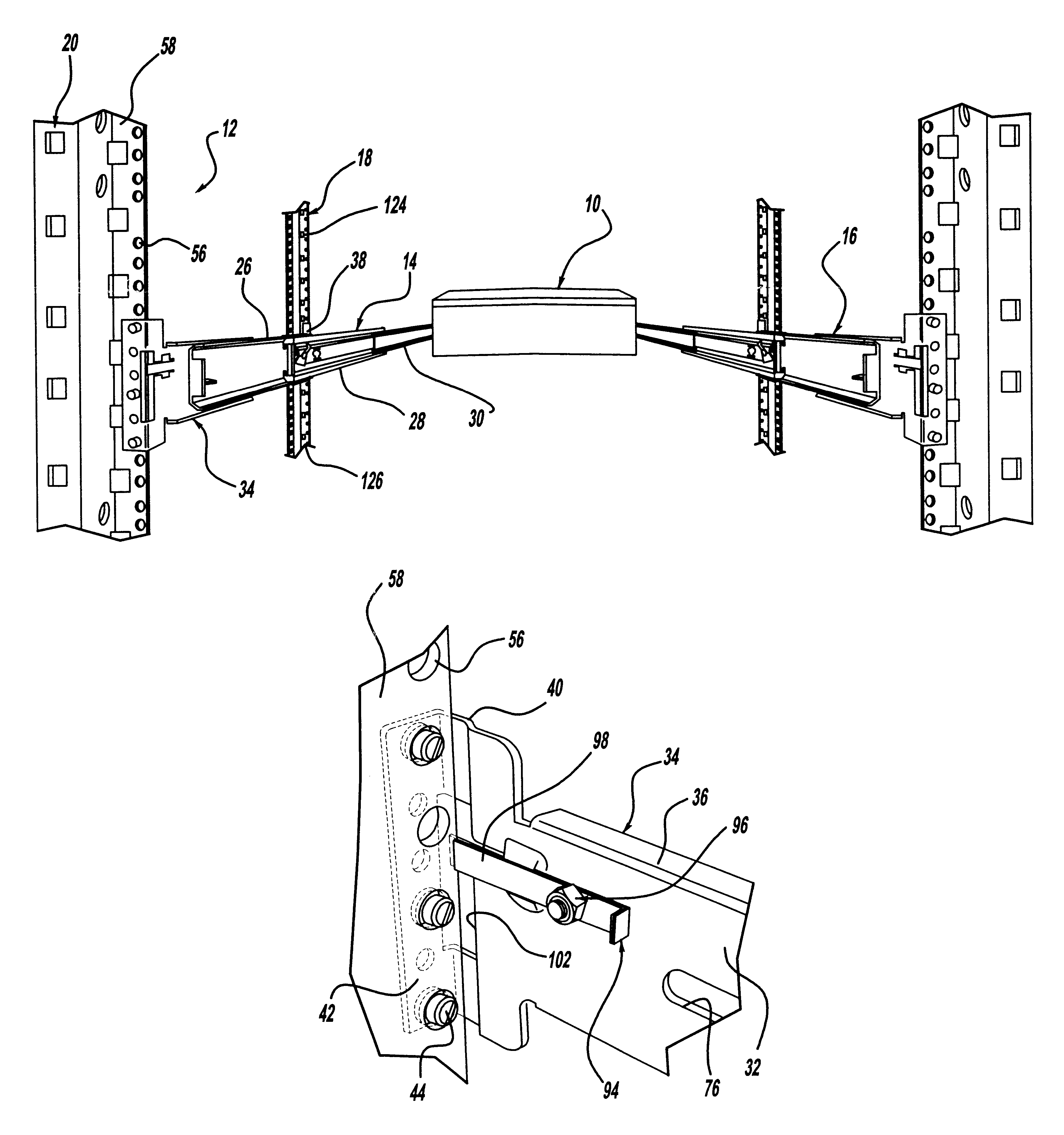
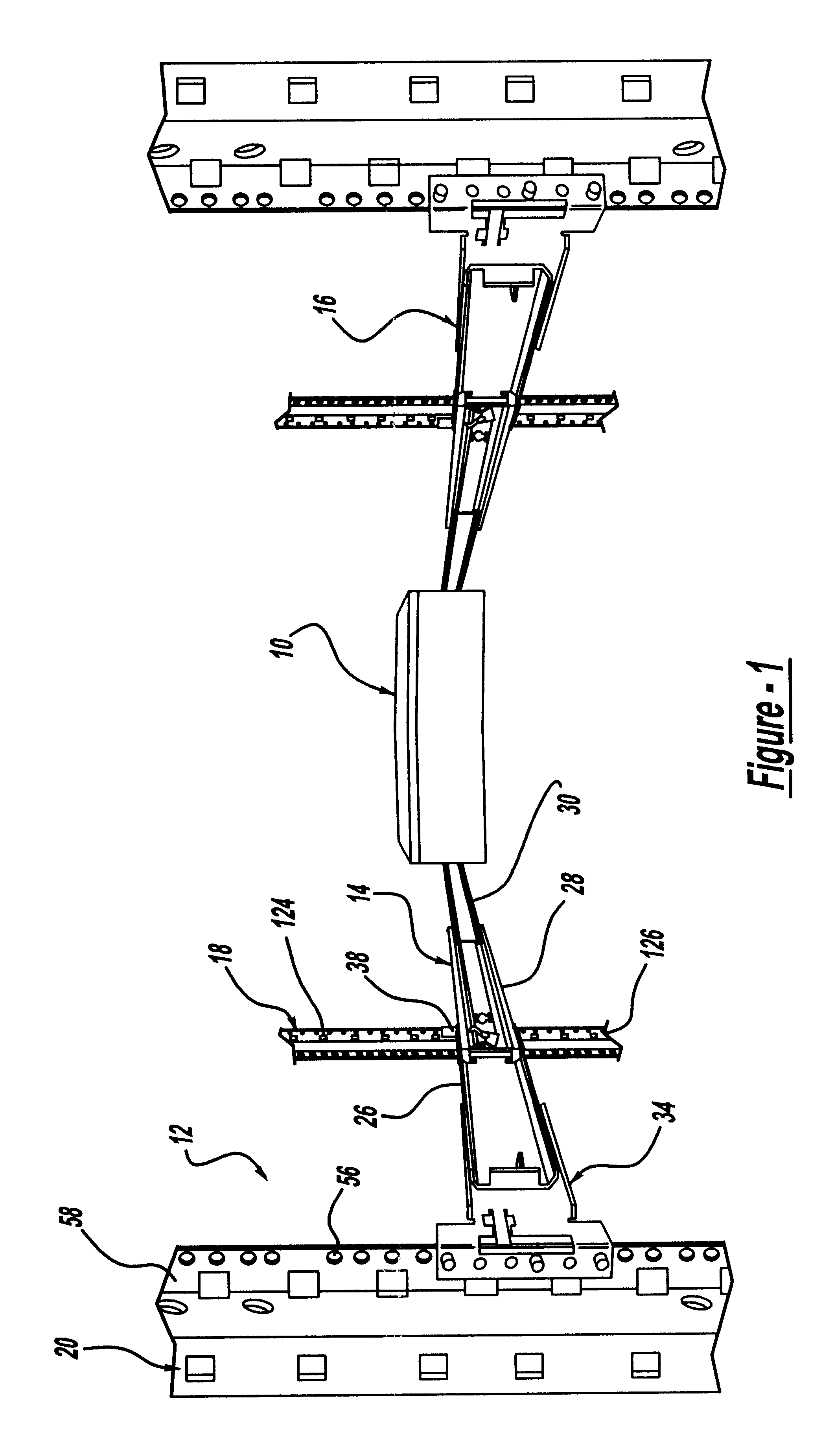
FIG. 1 is a rear perspective view of a computer server unit 10 mounted to a computer rack 12 by a pair of opposing slide assemblies 14 and 16. The rack 12 includes front columns 18 and rear columns 20 having a particular column configuration for this purpose, as is well understood in the art. The server unit 10 is shown in a fully extended position, where it has been slid out of a front of the rack 12 on the slide assemblies 14 and 16. In this orientation, a technician can gain access to the server unit 10 while it is still mounted to the rack, and in operation. The slide assembly 14 will be discussed herein, with the understanding that the slide assembly 16 is identical.

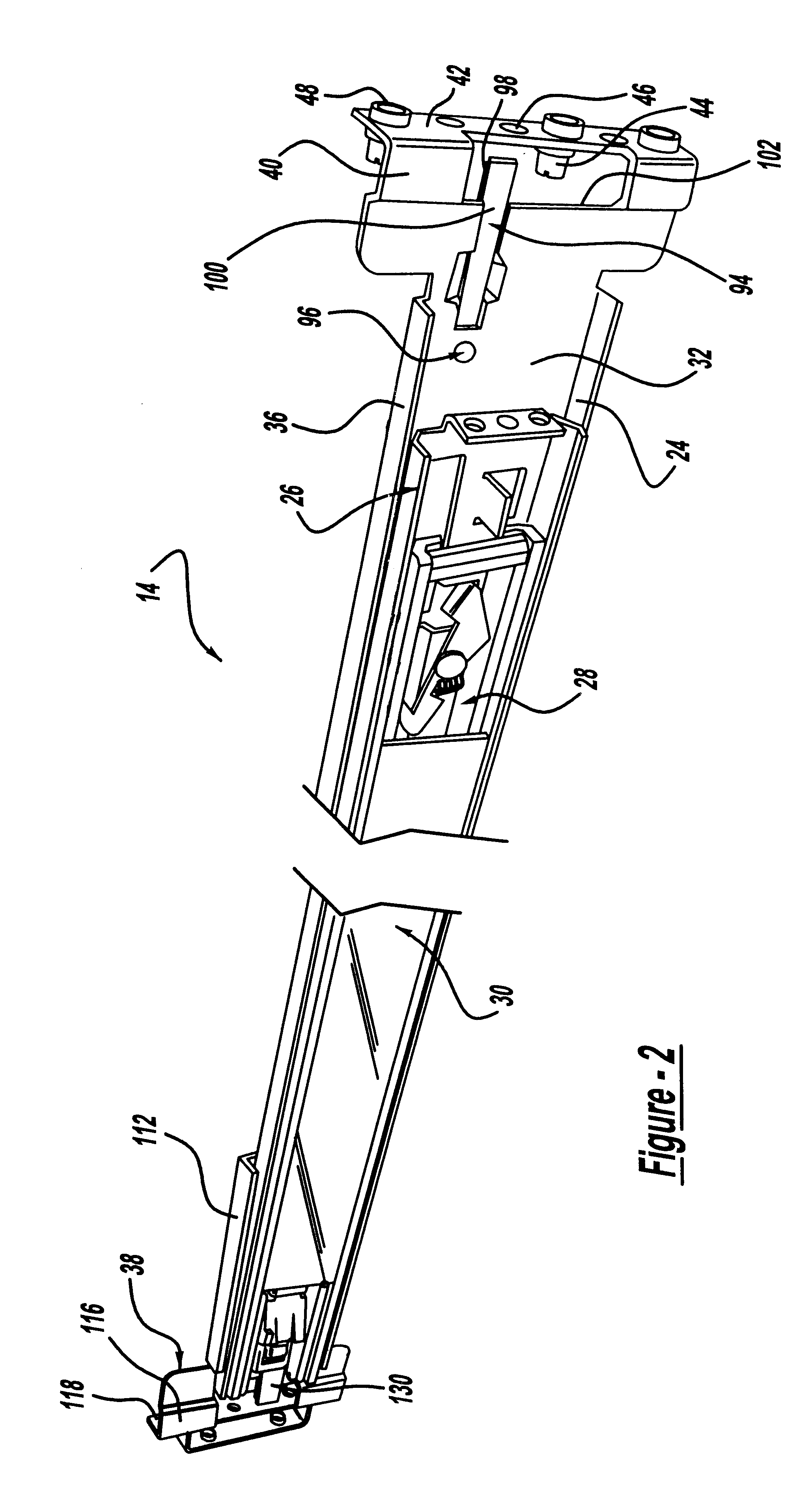
The slide assembly 14 includes a stationary member 26, an interm...


PUM


Abstract

A slide assembly for slidably mounting a computer server unit to a rack. The slide assembly includes a stationary member and at least one slidable member slidably mounted thereto. A front bracket is mounted to a front end of the stationary member and a rear bracket is mounted to a rear end of the stationary member. Both the front and rear brackets include a plurality of mounting pins and a spring element. The mounting pins are positioned within holes in the rack columns and the spring element applies a bias force against the rack column to hold the slide assembly to the rack.

Description

This application is related to application Ser. No. 10 / 003,278, titled "Dual Flat Springs for Tool-Less Slide Installation" filed Dec. 6, 2001.1. Field of the InventionThis invention relates generally to a slide assembly for slidably mounting a computer server to a rack and, more particularly, to a slide assembly for slidably mounting a computer server to a rack where the slide assembly includes a spring element mounted to front and back attachment brackets of the slide assembly to allow installation of the slide assembly to the rack columns without the need for tools.2. Discussion of the Related ArtCertain computer systems, such as computer network systems, typically include many separate computer units or servers that are positioned and stacked relative to each other in a rack. The various computer servers in the system are electrically interconnected and provide various functions, such as storage, communications, calculations, etc. The rack includes a plurality of support columns...

Claims


Application Information

Patent Timeline
Patent Type & Authority Patents(United States)
IPC IPC(8): A47B88/04H05K7/14
CPCA47B88/044H05K7/1421A47B88/43H05K7/1489
Inventor LAUCHNER, CRAIG EABBOTT, RYANHINTZ, ROBERTZIEMINSKI, LARRY
Owner VALTRUS INNOVATIONS LTD
Why Eureka
Try Eureka