Reversible cutter bit

a cutter bit and rotary cutter technology, applied in the direction of twisting drills, manufacturing tools, flat surface machines, etc., can solve the problems of increasing the amount of time required to exchange bits within the rotary cutter tool, high cost of planes, and inability to accurately use planes

Inactive Publication Date: 2004-05-04
BLACK & DECKER INC
View PDF13 Cites 12 Cited by
  • Summary
  • Abstract
  • Description
  • Claims
  • Application Information

AI Technical Summary

Problems solved by technology

However, such planes are expensive, inaccurate and require significant skill to utilize.
More particularly, when a finish carpenter or trim carpenter must switch cutter bits, a significant amount of time is expended when the first bit must be removed from the rotary tool and replaced with a second bit.
If the bit is to be entirely removed from the cutter, often the collet must be significantly loosened, thus increasing the amount of time necessary to exchange bits within the rotary cutter tool.
Further, on a busy construction site, tools are often stored at a position far away from the area where work is actually taking place, which increases the amount of time it takes a carpenter to retrieve the required bit for use on the job site.
Additionally, as multiple bits are utilized on a job site, the risk of loss of the bit is much greater, thereby increasing project costs, as the carpenter will not only have to repurchase the bit, but will loose time as a result of the lost cutter bit.
The benefit of a single bit with multiple profiles cannot be understated, given the cost savings and convenience of such bits, but given that smaller rotary cutter tools have a relatively small base and are often held in one hand, the use of large bits creates a number of safely concerns, not the least of which is that a large bit and a very small tool may be difficult to control, creating an unsafe condition.

Method used


Image

  • Reversible cutter bit
  • Reversible cutter bit
  • Reversible cutter bit

Examples


Embodiment Construction

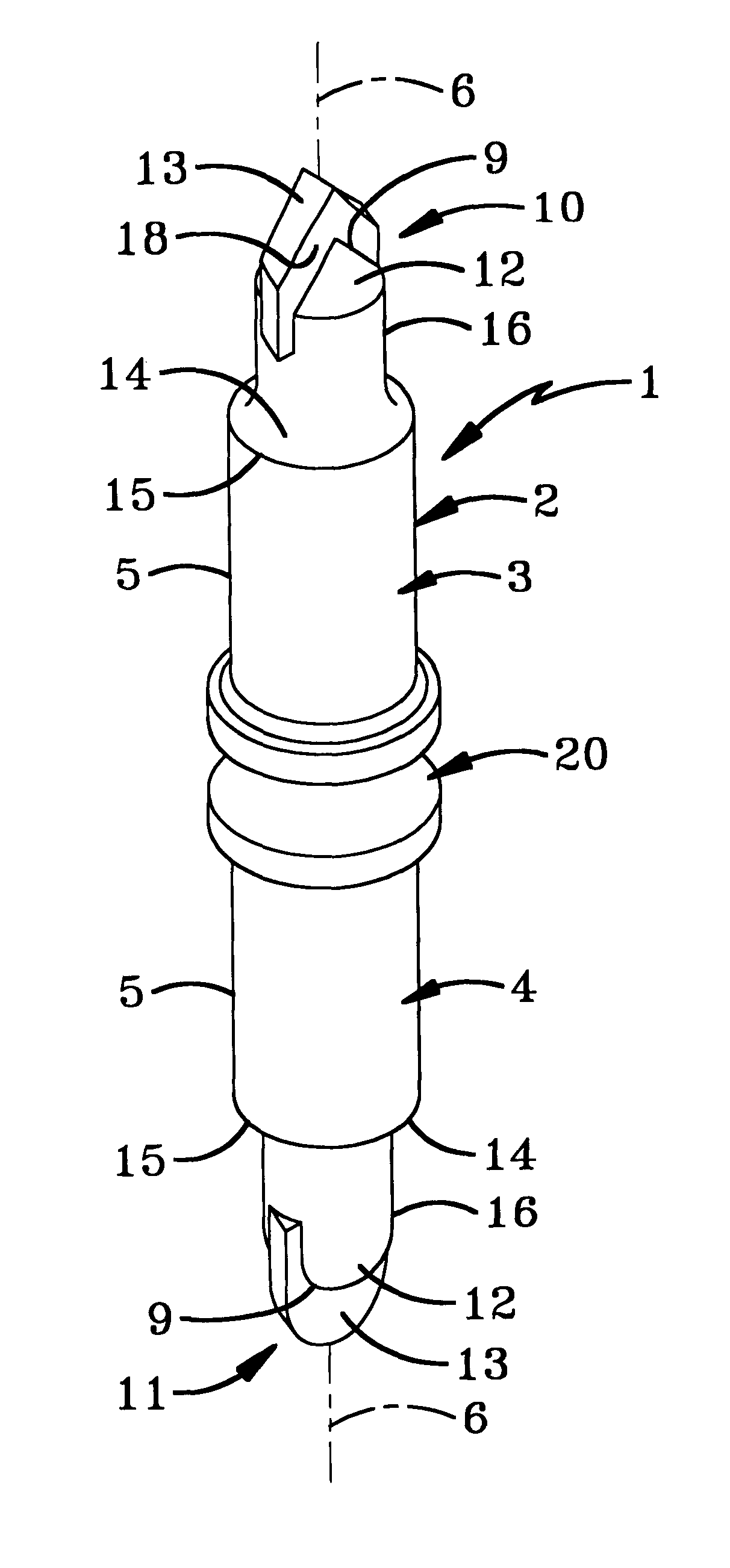
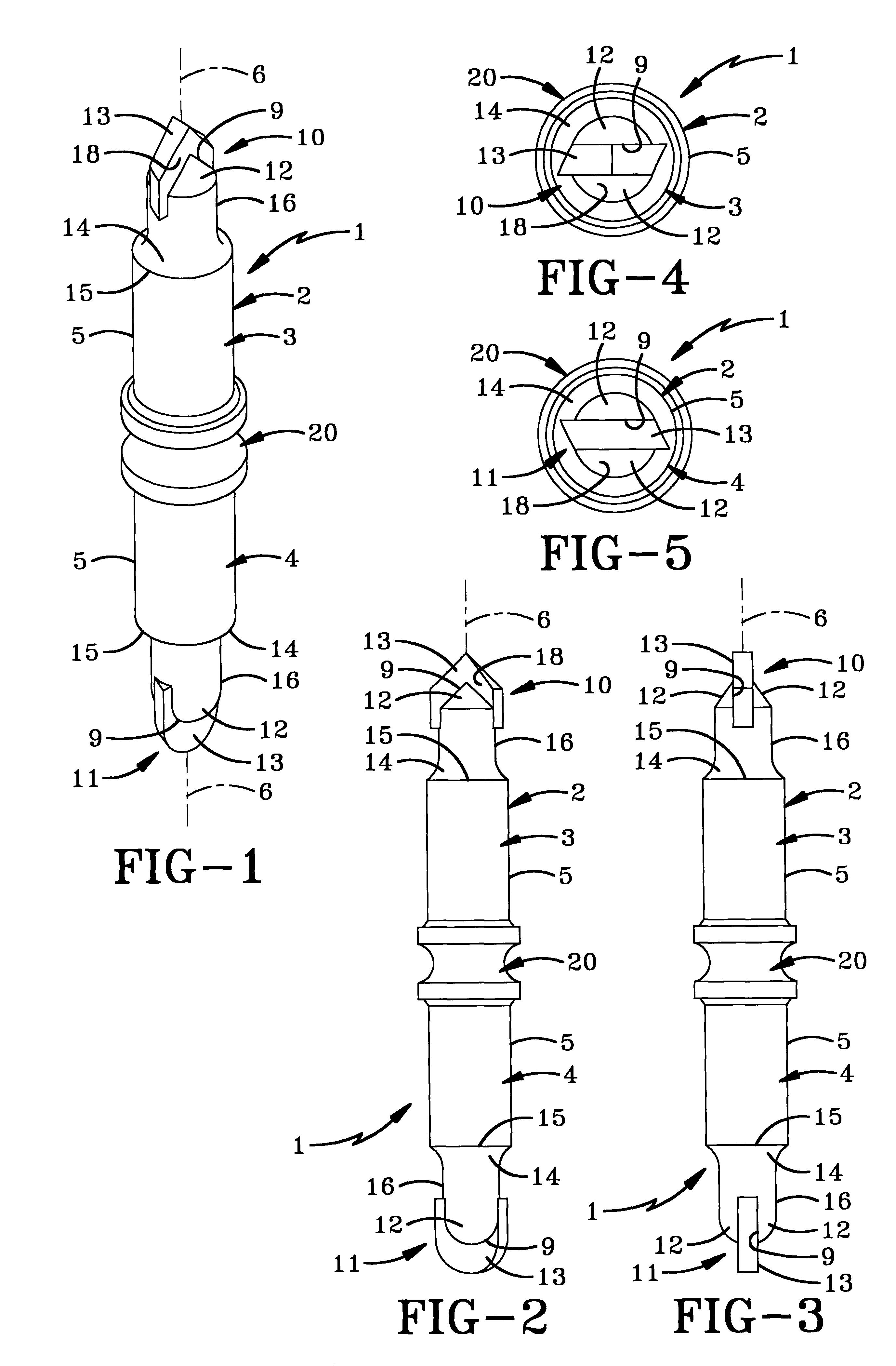
The improved cutter bit of the present invention is indicated generally at 1, and is shown particularly in FIG. 1. Cutter bit 1 includes a body 2 having a pair of axially aligned mounting shanks 3 and 4.

Body 2 is formed with an outer surface 5 and an axis of rotation 6.

Additionally, mounting shank 3 includes cutting region 10 and mounting shank 4 includes cutting region 11. Each cutting region 10 and 11 is formed with a pair of cutter flanges 12 for retaining a cutting blade 13. Cutter flanges 12 are parallel and spaced apart and extend outwardly away from mounting shanks 3 and 4 respectively. Cutter flanges 12 define a recess 9 which is complimentarily shaped to a portion of cutter blade 13. Cutter blade 13 is then welded or otherwise attached within recess 9 and may take a variety of sizes and configurations without departing from the spirit of the present invention. A shoulder 14 extends between each mounting shank 3 and 4 and cutting regions 10 and 11 respectively. Shoulder 14 h...


PUM

PropertyMeasurementUnit
lengthaaaaaaaaaa
diameteraaaaaaaaaa
surface areasaaaaaaaaaa

Abstract

A cutter bit is provided which includes a body having a pair of free ends with a cutter bit mounted adjacent each free end. A boss extends outwardly from the center of the body such that a portion of the body and the cutter bit may be mounted in a rotary cutting tool to allow the second cutter bit to be utilized. The bit is reversible such that either cutter bit may be positioned within the chuck of a rotary cutter tool while the cutter bit mounted on the opposite side of the body is utilized. A method of mounting a cutter bit in a rotary cutter tool is also provided which includes steps of loosening the bit within the chuck of the rotating cutting tool, removing the bit from the chuck, rotating the bit end to end, replacing the end of the bit that was out of the chuck originally into the chuck, and tightening the chuck.

Description

1. Technical FieldThe invention relates to an improved cutter bit. More particularly, the invention relates to shaft mounted rotary cutter bits of the type mounted in rotary woodworking machines. Specifically, the invention relates to multi-edged rotary cutting bits having multiple profiles on a single bit.2. Background InformationIt is customary in building construction, as well as the construction of furniture and cabinetry to impart decorative profiles upon the wood. Moreover, many joints are created by imparting a variety of profiles on the wood to create stronger joints, as well as to provide increased surface areas for glue contact at the joint. Regardless of the reason for imparting a profile on the wood, the profile may be created in one of two methods. Hand planes may be utilized, which planes have a cutting knife shaped with a negative of the profile to be imparted on the wood. However, such planes are expensive, inaccurate and require significant skill to utilize. As such...

Claims


Application Information

Patent Timeline
Patent Type & Authority Patents(United States)
IPC IPC(8): B23B51/00
CPCB23B51/00B23B2251/247Y10T408/907Y10T407/19Y10T408/909Y10T409/30952Y10T408/95Y10T408/34Y10T407/1948Y10T409/306608Y10T408/03Y10T408/348
Inventor DOLLAR, TAMMY ELAINEYEAGER, ROBERT WILLIAMHALL, ROBERT GLENN
Owner BLACK & DECKER INC
Why Eureka
Try Eureka