Electrode

a technology of electrodes and electrodes, applied in the field of electrodes, can solve the problems of electrolysis reaction, containing gas supplied, and having a theoretical cell voltage of 2.24 v, and achieve the effects of preventing unwanted oxidation processes, preventing any substantial fluctuation in cell voltage or current density, and ensuring stable operation of the electrolytic cell

Inactive Publication Date: 2004-05-11
AKZO NOBEL NV
View PDF22 Cites 14 Cited by
  • Summary
  • Abstract
  • Description
  • Claims
  • Application Information

AI Technical Summary

Benefits of technology

It has been surprisingly found that the problems referred to above concerning unwanted catalytic oxidation of the material in the hydrophilic layer can be solved by providing a barrier layer between the hydrophilic and reaction layers. The barrier layer thus provides a barrier preventing unwanted oxidation processes to occur by impeding contact between the two layers. The barrier layer also secures stable operation of the electrolytic cell, in which the gas diffusion electrode is arranged, thereby preventing any substantial fluctuation in cell voltage or current density. Moreover, it has been found that the inventional gas diffusion electrode can be operated substantially without any other deteriorating effects. The barrier layer further provides good adhesion to its adjacent layers.

Problems solved by technology

This electrolysis reaction, having a theoretical cell voltage of 2.24 V, requires a considerable amount of energy.
In previously employed partitioned electrolytic cell arrangements, wherein gas diffusion electrodes have been directly contacted to an ion exchange membrane, dividing the electrolytic cell into a cathode compartment and an anode compartment, electrolyte flooding problems have been faced due to the fact that the diffusion of oxygen-containing gas supplied to the gas diffusion electrode has been impeded by electrolyte present in the cathode compartment.
In this type of electrode arrangements, however, it has been noticed that the catalytic material present in the reaction layer of the electrode in contact with the hydrophilic layer, undesirably catalyses an oxidation reaction of the hydrophilic layer, usually comprising carbon, which causes formation of carbonates.
Carbonates, in turn, undesirably increase the hydrophilicity of the hydrophobic gas diffusion layer, leading to a decreased diffusion of supplied gas to the reaction layer of the electrode.
This fact results in an increase of the cell voltage and destabilises the operation of the electrolytic cell.

Method used


Image

  • Electrode
  • Electrode
  • Electrode

Examples


example 1

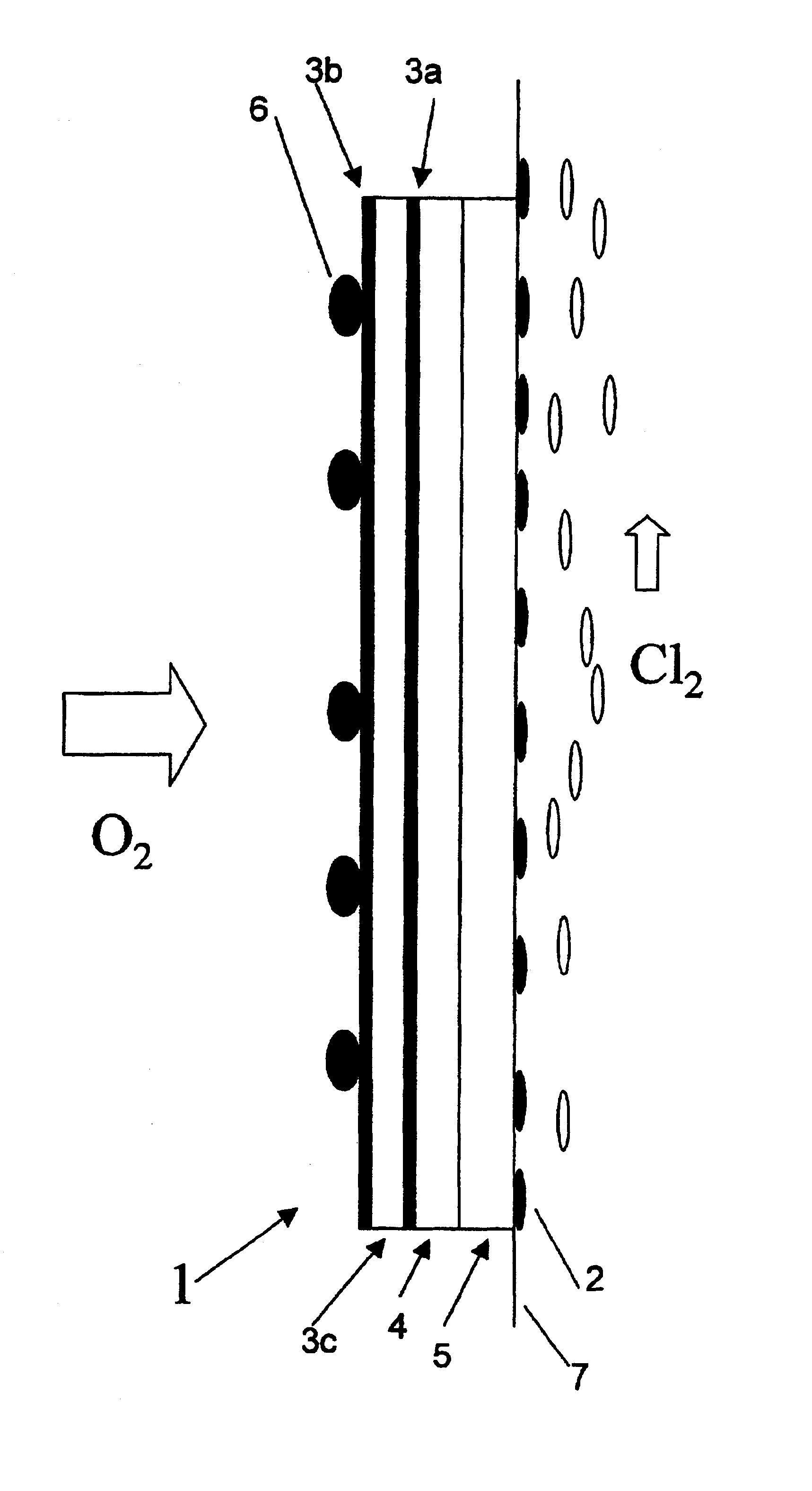
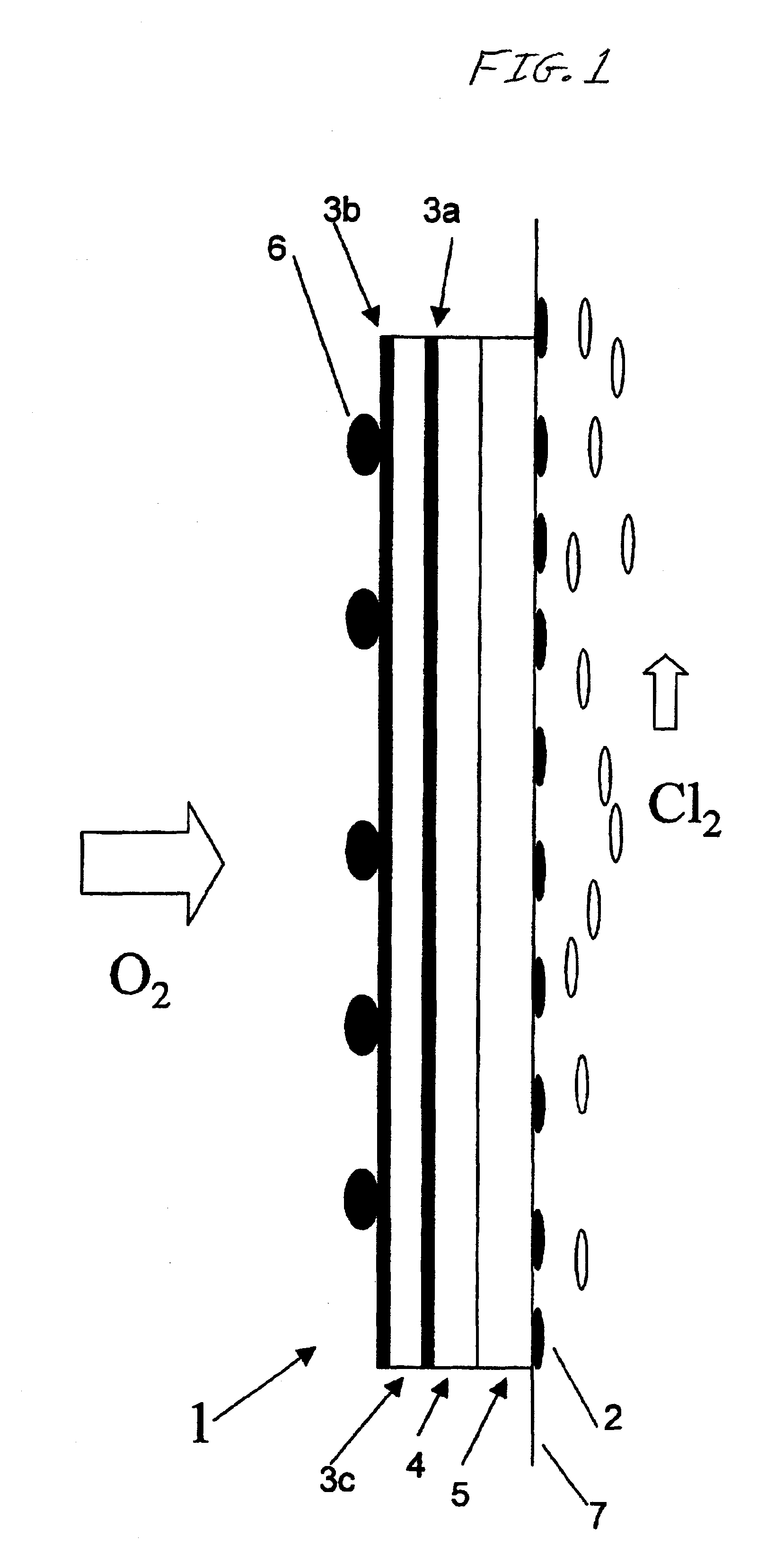
A 0.3 mm thick expanded silver mesh was prepared from a 0.1 mm thick silver plate, which was used as electrode substrate in a gas diffusion electrode. The gas diffusion electrode was subsequently manufactured in the following way:

1) A silver powder paste solution consisting of particles ranging from 0.5-1 .mu.m was spread over a silver mesh, which was subsequently dried.

2) Following drying, the electrode substrate was sintered in air at a temperature of 450.degree. C. for 30 minutes.

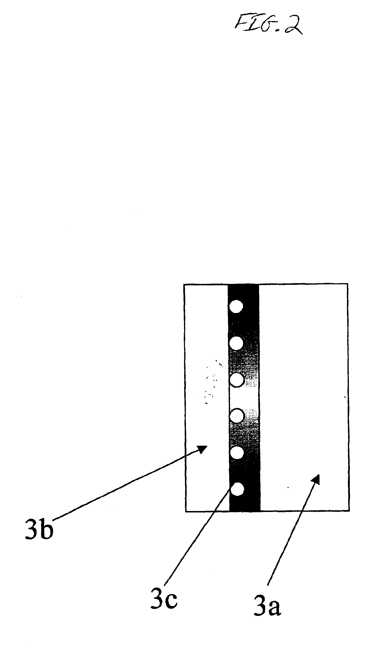
3) Dinitro diammine platinum salt dissolved in an alcohol solution, containing 50 g Pt / liter, was subsequently applied to one side of the prepared electrode substrate and baked at 350.degree. C. in nitrogen gas atmosphere for 10 minutes, thereby forming a platinum-coated gas diffusion electrode.

4) 2-propyl tetrabuthoxi zirconium, i.e. Zr(C.sub.3 H.sub.5 O).sub.4 solution, was applied to the same substrate side as the platinum solution, whereafter the electrode was baked at 450.degree. C. for 10 minutes. ...

example 3

The gas diffusion electrode was made as in example 1. On the front surface of the reaction layer, a graphite carbon cloth available from Toho Rayon Company Limited was soaked in the zirconium dioxide solution of example 1 and attached to the gas diffusion electrode with the ZrO.sub.2 side facing the reaction layer. The formed electrode was subsequently dried at 250.degree. C. for 3 hours. The electrode was then heated to 450.degree. C. in an oven for 30 minutes. Following heat treatment, the electrode was cooled to 25.degree. C., PTFE solution was subsequently applied to the back surface of the gas diffusion electrode and baked at 250.degree. C. for 30 minutes. A gas diffusion electrode having a porous hydrophilic layer was thereby obtained. The obtained gas diffusion electrode was submitted to the same electrolysis test as in example 1. The results showed a cell voltage of 2.02-2.05 V at a current density of 40 A / dm.sup.2 at 90.degree. C. No deterioration in electrolysis was observ...

example 4

The expanded silver mesh of example 1 was used to manufacture a gas diffusion electrode. Silver paste comprising silver powder as of example 1, 20% PTFE (30 NE available from Dupont) was applied on the mesh to make it porous. On one side of the plate, an additional amount of 20% PTFE was applied. The obtained electrode was dried and heated to 200.degree. C. for 10 minutes. It was subsequently pressed at 5 kg / cm.sup.2 at 150.degree. C. for 10 minutes. The electrode of the gas diffusion electrode was then coated with a hexachloro platinate 2-propyl alcohol solution on the opposite side of the PTFE side and subsequently heated at 300.degree. C. for 30 minutes. A 90 wt % ZrO.sub.2 paste comprising 10-20 .mu.m ZrO.sub.2 particles and 10 wt % PTFE (30 NE available from Dupont) were applied on the platinum side of the reaction layer followed by heating at 300.degree. C. in air for 15 minutes. The obtained gas diffusion electrode was submitted to the electrolysis test under the same conditi...


PUM

PropertyMeasurementUnit
cell voltageaaaaaaaaaa
temperatureaaaaaaaaaa

Abstract

The invention relates to a gas diffusion electrode (1) comprising a hydrophobic gas diffusion layer (3b), a reaction layer (3a), and a hydrophilic layer (5) arranged in the mentioned order wherein the reaction layer (3a) is arranged to a barrier layer (4), which barrier layer (4), on its opposite side, is arranged to the hydrophilic layer (5). The invention also relates to a method for manufacturing such a gas diffusion electrode (1), and to an electrolytic cell, and use thereof.

Description

The present invention relates to a gas diffusion electrode suitable for production of chlorine and alkali metal hydroxide. The invention also concerns a method for manufacturing such a gas diffusion electrode. The invention further concerns an electrolytic cell comprising such gas diffusion electrode and the use thereof.Electrolysis of alkali metal chlorides to produce chlorine and alkali metal hydroxide has been known for a long time.In the past, hydrogen evolving cathodes have been used for this purpose. The principal chemical reaction taking place in the electrolytic cell can be represented by the following scheme: 2NaCl+2H.sub.2 O.fwdarw.Cl.sub.2 +2 NaOH+H.sub.2. This electrolysis reaction, having a theoretical cell voltage of 2.24 V, requires a considerable amount of energy.Previously, also oxygen consuming gas diffusion electrodes have been disclosed for the production of chlorine and alkali metal hydroxide, as further described in e.g. U.S. Pat. No. 4,578,159. The term "gas d...

Claims


Application Information

Patent Timeline
Patent Type & Authority Patents(United States)
IPC IPC(8): C25B1/46C25B11/03C25B1/00C25B11/00
CPCC25B1/46C25B11/035C25B11/031
Inventor BUSSE, BERNDBERGMAN, LARS-ERIK
Owner AKZO NOBEL NV
Why Eureka
Try Eureka