Image forming apparatus, and process cartridge for use in image forming apparatus

a technology of image forming apparatus and process cartridge, which is applied in the direction of electrographic process apparatus, corona discharge, instruments, etc., can solve the problems of difficult control of the electric current flowing from the bias roller into the photoconductor, difficult improvement of the speed of image formation, and high equipment cos

Inactive Publication Date: 2004-05-25
RICOH KK
View PDF44 Cites 71 Cited by
  • Summary
  • Abstract
  • Description
  • Claims
  • Application Information

AI Technical Summary

Problems solved by technology

However, in order to repeat the image formation two or more times (usually 4 times) using one photoconductor and to form a full color image, the improvement in the speed of image formation is difficult.
On the other hand, in the case of the tandem type, the scale of the equipment becomes large, which causes a problem that the equipment becomes expensive.
In a conventional indirect transfer method, if the diameter of each of the photoconductors and the distances between the photoconductors are reduced in order for the miniaturization and cost saving, it becomes difficult to control the electric current which flows from the bias roller into the photoconductor.
The intermediate transfer belt is usually made of a material with middle resistance, and when changes of resistance and electrostatic capacitance according to the environment cause the electric current i2 to fluctuate, it is very difficult to maintain the transfer conditions of the intermediate transfer belt uniformly by keeping the electric current i1 constant.
The electric current control will become more difficult in such a case.
There is a problem that an undesired image which lacks the toner corresponding to the spot is formed on the recording paper.
However, according to this method, the transfer accuracy at the time of transferring of a toner image from the photoconductor to the recording medium will become worse, and dot reproducibility and thin-line reproducibility will degrade.
Therefore, although the speed difference has arisen not a little in the surface speed of the photoconductor and the recording medium by these factors, establishing the speed difference intentionally at the surface speed of the photoconductor and the recording medium will cause degradation of the image quality.
Moreover, the surface abrasion loss of the four photoconductors by the repetition image output in the tandem type image forming apparatus is not uniform.
If the cancellation of such strain due to the slippage becomes severe, it will cause a banding image to appear, and will become a factor of degradation of the image quality.
In addition, the transfer of a color image using the conventional resin belt has the following problem.
Moreover, there is an increasing demand of attaching irregularity to various copy sheets, including Japanese paper, in forming an image by a full color image forming apparatus.
However, in a case of a copy sheet with poor flatness, the toner and the opening tend to be created at the time of image transfer, and the omission of image transfer becomes easy to occur.
Since the hardness of the elastic belt is lower than the hardness of a resin belt, the elastic belt easily deforms at the transfer unit corresponding to the toner layers and the recording sheet with poor flatness.
If the thickness of the elastic layer is too thick, the surface expansion and contraction will become large and a crack will become easy to generate it on the surface.
Moreover, since the amount of expansion and contraction becomes large, it is unsuitable that the thickness of the elastic layer is too large (about 1 mm or more).
This problem arises from that it is easy to receive shrinkage and expansion at the time of molding.
Moreover, a general method is to make the oil component contain to the base material when making it soft, if the continuation actuation is carried out in the state of pressurization, it has a difficulty that the oil component oozes out.
The oil adhesion over the photoconductor can be reduced, but the effect of transfer property improvements, such as the omission of character inside, is not obtained.
Moreover, firm bridging to the firm-bridging roller becomes difficult.
However, although the surface part of the latent image support stops almost abrading out generally when the wear resistance of the latent image support is raised, by the reactant gas which occurs at the time of charging, such as ozone and NOx, the surface part will form low resistance, the electrostatic load of the surface part will no longer be retained gradually, and the electrostatic load will transfer in the direction of the surface.
The wear resistance may become inadequate when the average of the primary grain size of the filler is below 0.01 micrometers.
On the other hand, when the average of the primary grain size of the filler is above 0.5 micrometers, the light irradiated to the latent image support may be scattered by the filler, the permeability may fall, and the problem of image dotage or character thickening may arise.
However, on the other hand, the toner is not easily attached to the photoconductor surface, and a desired picture quality may not be obtained.
It becomes difficult to scratch or remove the low-resistance discharge products that are generated at the time of charging and adhere to the photoconductor surface.
The above problem of banding images arises, or it may become the cause of the undesired spot image by the decline of the transfer efficiency.

Method used


Image

  • Image forming apparatus, and process cartridge for use in image forming apparatus
  • Image forming apparatus, and process cartridge for use in image forming apparatus
  • Image forming apparatus, and process cartridge for use in image forming apparatus

Examples


example 2

(EX 2)

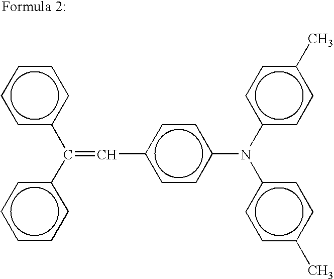
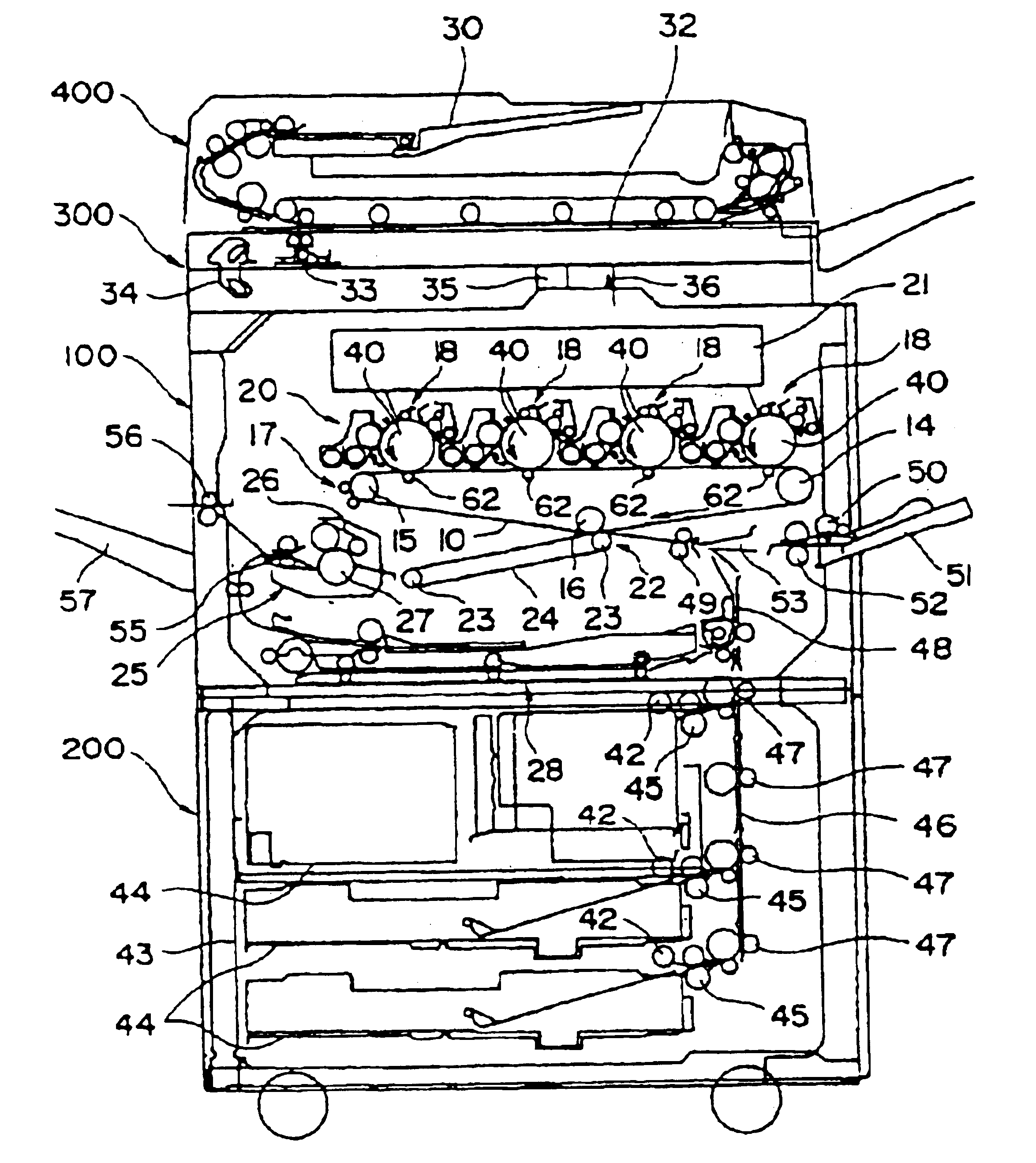
The charge transportation substance of 3 weight parts of the above Formula 2 is added to the coating liquid for the protection layer of the Example 1, and it is considered as the coating liquid for the protection layer. The four electrophotographic photoconductors are produced in a similar manner to the Example 1. They are incorporated in the image forming apparatus of FIG. 1, and the same image evaluation as the Example 1, including the abrasion loss measurement and the coefficient of friction measurement, is performed.

example 3

(EX 3)

The four electrophotographic photoconductors are produced in a similar manner to the Example 2, except having used the titanium-oxide particles for the coating liquid for the protection layer in the Example 2, instead of the alumina particles. They are incorporated in the image forming apparatus of FIG. 1, and the same image evaluation as the Example 2, including the abrasion loss measurement and the coefficient of friction measurement, is performed.

example 4

(EX 4)

The four electrophotographic photoconductors are produced similar tot he Example 2 except having used the silica particles for the coating liquid for the protection layer of the Example 2 instead of the alumina particles. They are incorporated in the image forming apparatus of FIG. 1, and the same image evaluation as the Example 2, including the abrasion loss measurement and the coefficient of friction measurement, is performed.


PUM


Abstract

An image forming apparatus comprises a latent image support which supports an electrostatic latent image. A charging unit charges a surface of the image support. A latent image formation unit forms an electrostatic latent image on the image support surface. A developing unit develops the latent image with toner to form a toner image. A transfer unit transfers the toner image from the image support to a recording medium. A transport unit transports the recording medium so that the image support surface is countered to a surface of the recording medium. The surface of the image support has a coefficient of friction ranging from 0.1 to 0.7 according to Euler belt method, and a difference between a speed of the image support and a speed of the recording medium is below 1%, and the image support has an outermost surface containing a filler and a binder resin.

Description

1. Field of the InventionThe present invention relates to an image forming apparatus, such as a copier, a printer or a facsimile, and relates to a process cartridge used for the image forming apparatus. More specifically, the image forming apparatus of the present invention includes a plurality of image formation units. Each image formation unit includes a latent image support for supporting an electrostatic latent image, and a charging unit for charging the latent image support surface. A latent image formation unit forms an electrostatic latent image on the latent image support. A developing unit develops and forms the electrostatic latent image into a toner image. A transfer unit transfers the toner image on the latent image support to a recording medium. Moreover, the present invention relates to a process cartridge used for the image forming apparatus having the plurality of image formation units each equipped with the recording medium surface side the transfer unit to which th...

Claims


Application Information

Patent Timeline
Patent Type & Authority Patents(United States)
IPC IPC(8): G03G15/01
CPCG03G15/0194G03G2215/00962G03G2215/0119G03G2221/183
Inventor SUGINO, AKIHIROSAWAI, YUUJITAKAHASHI, MITSURUKATOH, KOHKIKAWAGOE, KATSUYAOGIYAMA, HIROMITAMIYA, TAKAHIRO
Owner RICOH KK
Why Eureka
Try Eureka