Process cartridge and electrophotographic image forming apparatus

a technology of electrophotographic image and process cartridge, which is applied in the direction of electrographic process apparatus, instruments, optics, etc., can solve problems such as liable damage, and achieve the effect of small size and small siz

Active Publication Date: 2009-01-01
CANON KK
View PDF88 Cites 72 Cited by
  • Summary
  • Abstract
  • Description
  • Claims
  • Application Information

AI Technical Summary

Benefits of technology

[0008]The primary object of the present invention is to provide a process cartridge, the electrophotographic photosensitive drum and development roller of which can be placed in contact with, or separated from, each other, and which is significantly smaller in size than a counterpart in accordance with the prior art, and also, to provide an electrophotographic image forming apparatus which is compatible with a process cartridge in accordance with the present invention, is removably mountable and is significantly smaller in size than a counterpart in accordance with the prior art.
[0009]Another object of the present invention is to provide a process cartridge, the electrophotographic photosensitive member and development roller of which can be placed in contact with, or separated from, each other, and the development unit moving force receiving portion of which is significantly less liable to be damaged while the process cartridge is handled by a user, or transported alone, than a counterpart in accordance with the prior art.

Problems solved by technology

Therefore, it is liable to be damaged while a user handles a process cartridge, or a process cartridge is conveyed alone.
Further, the presence of the above described force receiving portion has been one of the major problems which arose when studies were made to reduce in size a process cartridge structured so that its electrophotographic photosensitive member and development roller can be placed in contact with, or separated from, each other, and also, when studies were made to reduce in size the main assembly of an image forming apparatus in which such a process cartridge as the one described above is removably mountable.

Method used


Image

  • Process cartridge and electrophotographic image forming apparatus
  • Process cartridge and electrophotographic image forming apparatus
  • Process cartridge and electrophotographic image forming apparatus

Examples


embodiment 1

[0032]Next, referring to FIGS. 1-4, the process cartridges and electrophotographic image forming apparatuses in this preferred embodiment of the present invention will be described.

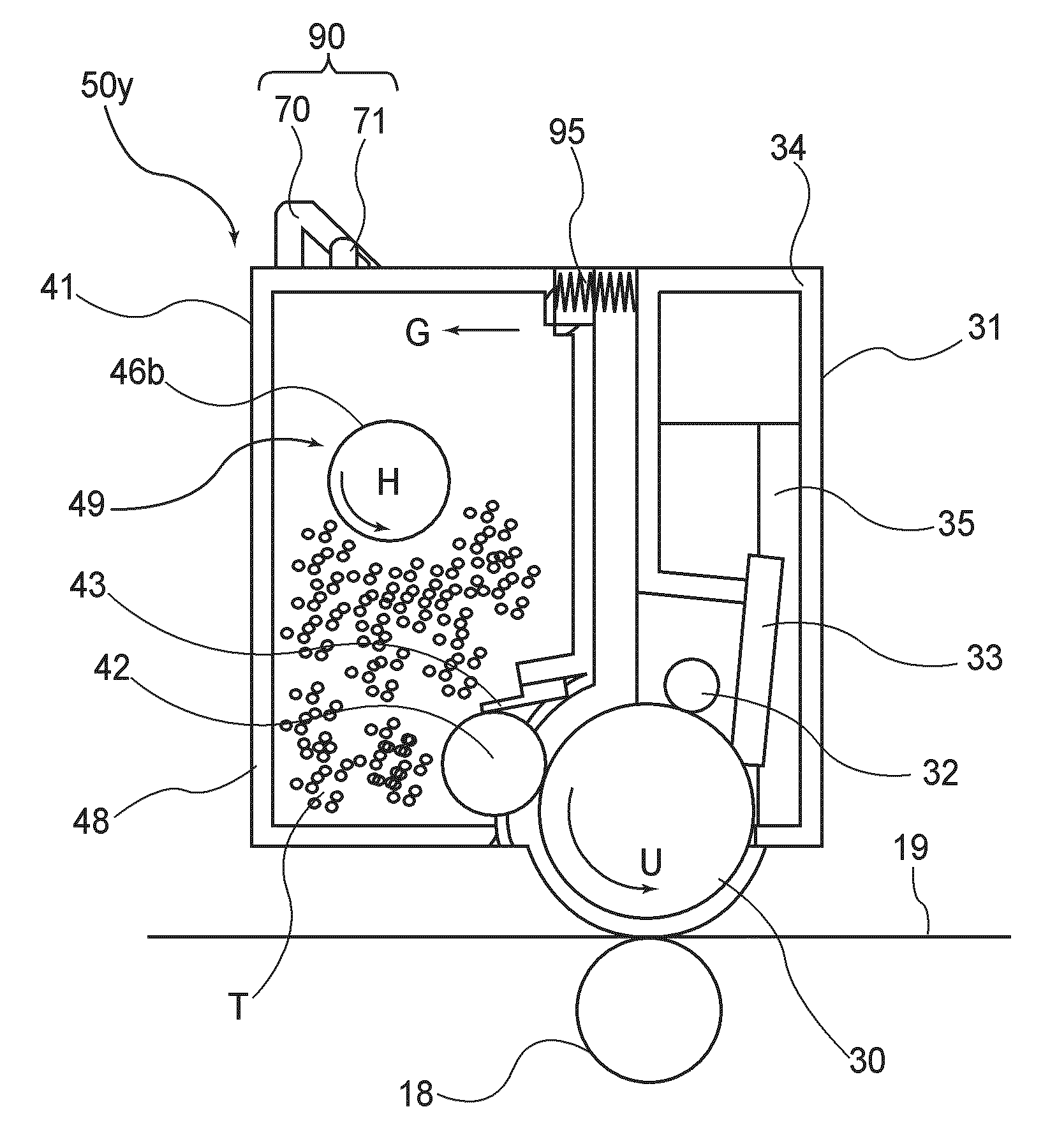
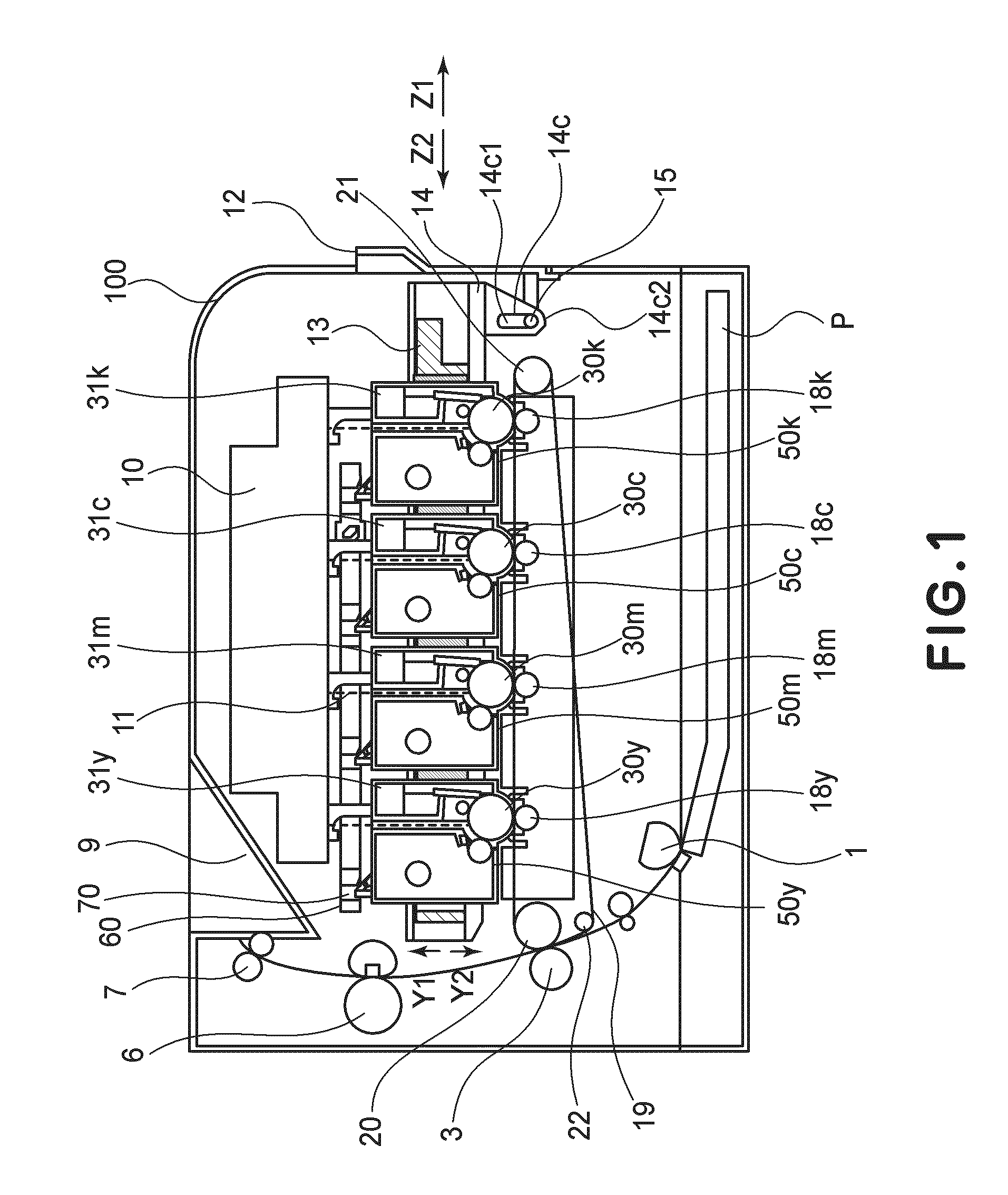
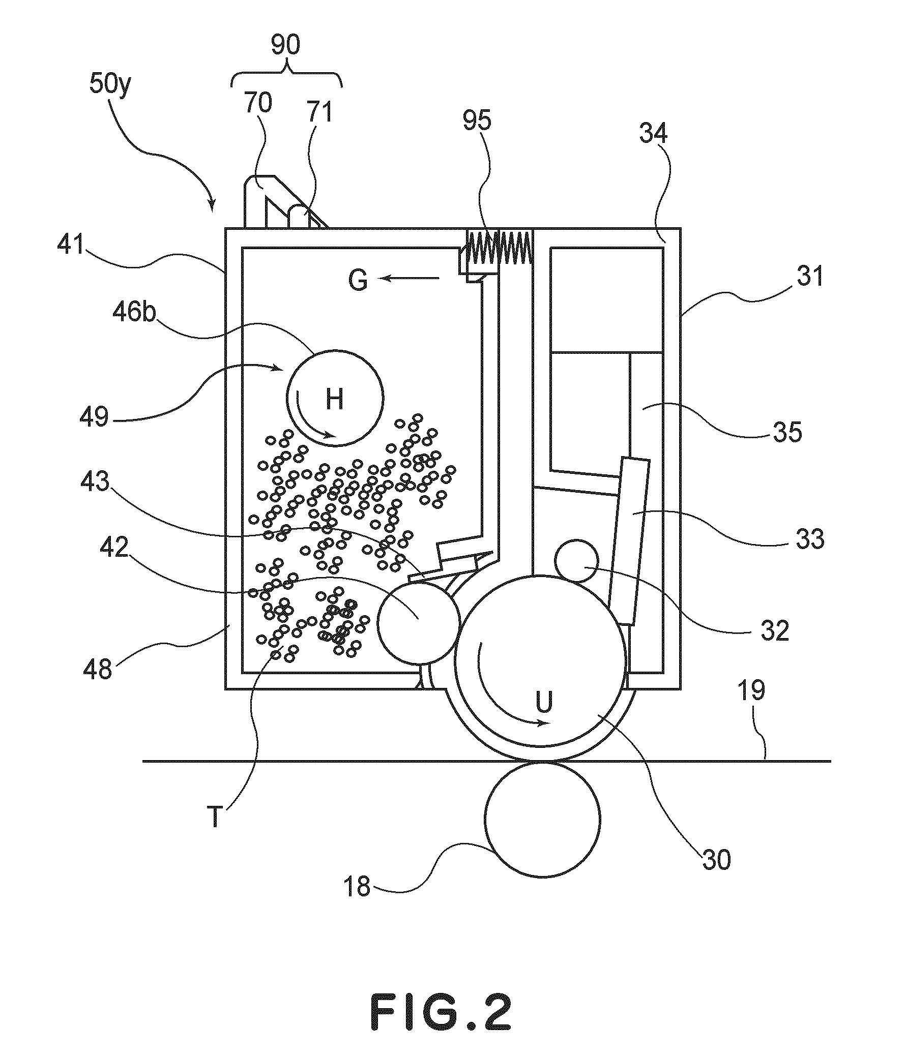
[0033]FIG. 1 is a schematic sectional view of the electrophotographic image forming apparatus 100 (which hereafter will be referred to simply as apparatus main assembly), in which multiple (four) process cartridges 50y, 50m, 50c, and 50k (which hereafter may be referred to simply as cartridges 50) which have been removably mounted. The multiple (four) cartridges 50 store yellow, magenta, cyan, and black toners (developers), one for one. FIG. 2 is a schematic sectional view of the cartridge itself. FIGS. 3 and 4 are schematic sectional drawings of the electrophotographic image forming apparatus in this embodiment, which are for showing how the any cartridge or cartridges 50 are removed from the main assembly of the image forming apparatus.

{General Structure of Electrophotographic Image Forming Apparatus}

[0...

embodiment 2

[0080]Next, referring to FIGS. 12 and 13, another preferred embodiment of the present invention will be described. In this embodiment, the cartridge 50 is provided with a first lever 471, a second lever 470, and a gear 472. The first lever 471 has a force receiving first portion 471c. The second lever 470 has a force receiving second portion 470c, and meshes with the gear 472. This structural arrangement can move the second lever by a greater distance than the distance by which the first lever is moved.

[0081]The gear 472 is a step gear made up of a portion (first portion) which engages with the first lever 471 and is n1 in tooth count, and a portion (second portion) which engages with the second lever 470 and is n2 in tooth count. Thus, it is possible to amplify the distance by which the first level 471 is moved by making the tooth count n2 of the second portion of the gear 472 greater than the tooth count n1 of the first portion of the gear 472 (n2>n1). To concretely described the ...

embodiment 3

[0087]Next, referring to FIGS. 14 and 15, the third embodiment of the present invention will be described with reference to a case where the force receiving first member belongs to a drum unit 531. First, the method for assembling the cartridge in this embodiment will be described. The cartridge in this embodiment is designed so that a force receiving first member 571 belongs to a drum unit 531. A force receiving second member 570 and a connective rod 574 are attached to a cover 546. Then, the cover 536 is joined with a bearing member 545. Lastly, the development unit 541 and drum unit 531 are connected by the cover 536 to complete the cartridge 550.

[0088]To describe in more detail the cartridge 550 in this embodiment with reference to FIGS. 14 and 15, first, referring to FIG. 14, a projection 5180 of the apparatus main assembly is located so that it opposes the drum unit. Thus, the force receiving first member 571 is placed in the drum unit 531.

[0089]The drum unit is provided with ...


PUM


Abstract

A process cartridge detachably mountable to a main assembly of an electrophotographic image forming apparatus, includes an electrophotographic photosensitive drum; developing roller for developing an electrostatic latent image formed on the electrophotographic photosensitive drum; drum frame supporting the electrophotographic photosensitive drum; a developing frame supporting the developing roller, the developing frame is movable relative to the drum frame and is capable of taking a contacting position in which the developing roller is in contact with the electrophotographic photosensitive drum; and a force receiving device including a first force receiving portion for receiving a first external force and a second force receiving portion for receiving a second external force, wherein the second force receiving portion is movable relative to the developing frame, wherein the second force receiving portion is placed in a stand-by position retracted from an operating position by the first force receiving portion receiving the first external force, and is movable from the stand-by position to the operating position for moving the developing frame from the contacting position to the spacing position, wherein a distance through which the second force receiving portion moves from the stand-by position to the operating position is larger than a distance through which the first force receiving portion is moved by the first external force.

Description

FIELD OF THE INVENTION AND RELATED ART[0001]The present invention relates to a process cartridge made up of an electrophotographic photosensitive drum and a development roller (which processes photosensitive drum), in particular, a process cartridge, the electrophotographic photosensitive drum and development roller of which can be placed in contact with, or separated from, each other. The present invention also relates to an electrophotographic image forming apparatus employing the above described process cartridge.[0002]In recent years, a process cartridge system has come to be widely used in the field of an image forming apparatus which uses an electrophotographic image forming process. A process cartridge system is one of the electrophotographic image forming systems. It uses a cartridge in which an electrophotographic photosensitive drum, and a development roller, that is, a roller for processing an electrophotographic photosensitive drum, are integrally disposed to make them r...

Claims


Application Information

Patent Timeline
Patent Type & Authority Applications(United States)
IPC IPC(8): G03G21/16
CPCG03G21/1803G03G21/1825G03G21/181G03G21/1842
Inventor TOBA, SHINJIROYOSHIMURA, AKIRANITTANI, SUSUMU
Owner CANON KK
Why Eureka
Try Eureka