ATM switching apparatus applicable to short cell

a short cell and switching apparatus technology, applied in data switching networks, instruments, frequency-division multiplexes, etc., can solve the problems of asynchronous data transmission delay and communication quality drop, each short cell is not transmitted to a desired destination, and conventional atm switching apparatuses are not incorporated

Inactive Publication Date: 2004-06-29
FUJITSU LTD
View PDF6 Cites 6 Cited by
  • Summary
  • Abstract
  • Description
  • Claims
  • Application Information

AI Technical Summary

Problems solved by technology

For this reason, there is a fear that there occurs a delay in data transmission and a drop in communication quality.
However, upon transmitting the AAL2 cell by using the ATM connection as described above, there occurred the following problems.
Therefore, each short cell is not transmitted to a desired destination unless an ATM switching apparatus carries out switching per short cell.
However, conventional ATM switching apparatuses are not incorporated with a function of processing the short cells embedded in the payload of the ATM cell.
Therefore, switching per short cell could not be carried out.
However, the ensuring means for the switching operation for the short cell has not yet been established with respect to the AAL2.

Method used


Image

  • ATM switching apparatus applicable to short cell
  • ATM switching apparatus applicable to short cell
  • ATM switching apparatus applicable to short cell

Examples


embodiment 1

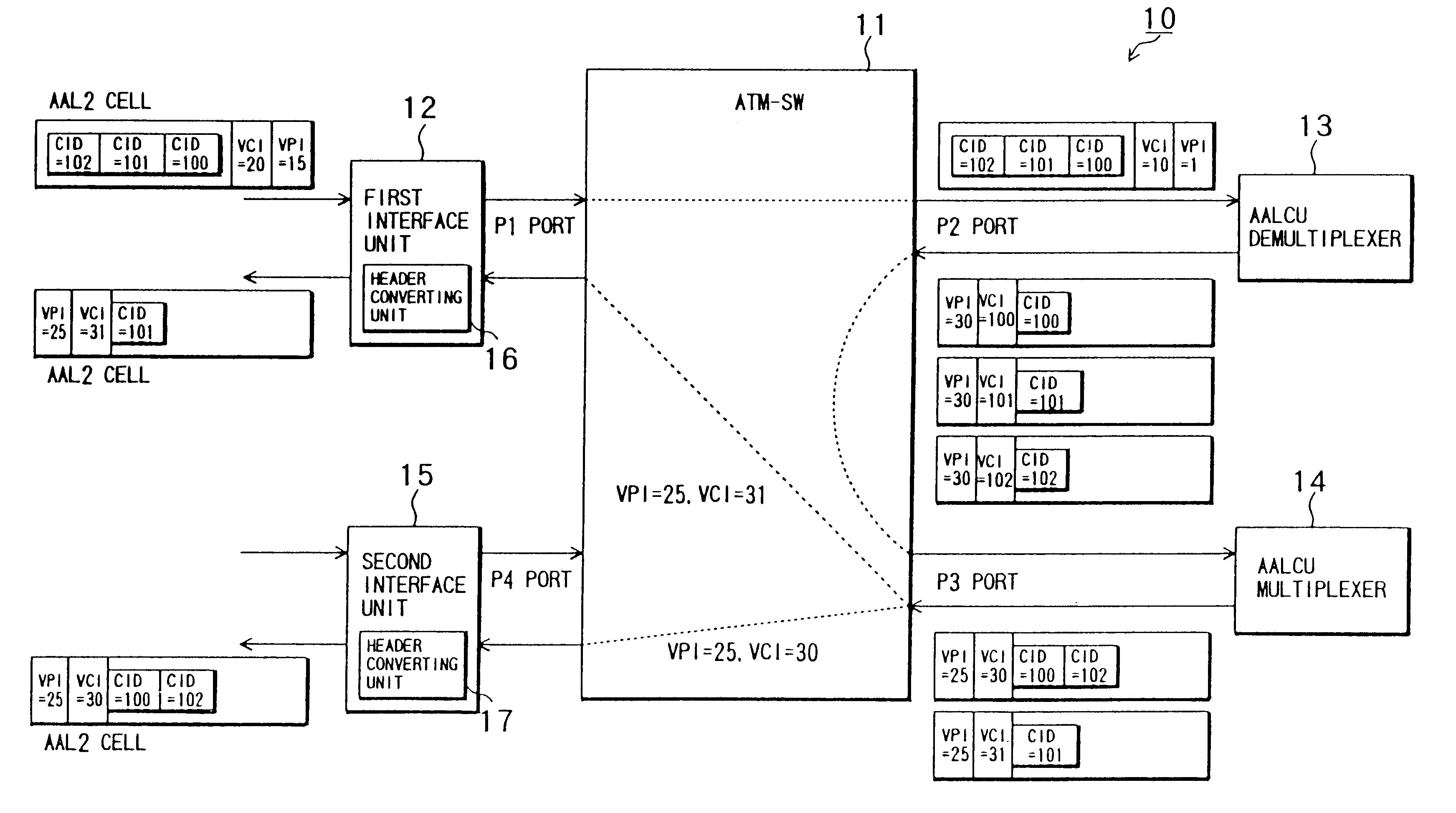
FIG. 1 is a diagram showing an ATM switching apparatus 10 applicable to a short cell in accordance with the In FIG. 1, an ATM switching apparatus 10 is comprised of an ATM-SW (self routing switch:ATM switch) 11, a first interface unit 12 connected to a P1 port of the ATM-SW 11, an AALCU demultiplexer (hereinafter referred to as demultiplexer) 13 connected to a P2 port of the ATM-SW 11, an AALCU multiplexer (hereinafter referred to as multiplexer) 14 connected to a P3 port of the ATM-SW 11, and a second interface unit 15 connected to a P4 port of the ATM-SW 11.

The ATM-SW 11 refers to VPI / VCI of a cell inputted thereinto, and outputs the cell from a given port. More specifically, a cell of VPI=1, VCI=10 is outputted from the P2 port; a cell of VPI=30 is outputted from the P3 port; a cell of VPI=25, VCI=31 is outputted from the P1 port; and a cell of VPI=25, VCI=30 is outputted from the P4 port.

An AAL2 cell (VPI=15, VCI=20) storing a plurality of short cells is inputted to the first i...

embodiment 2

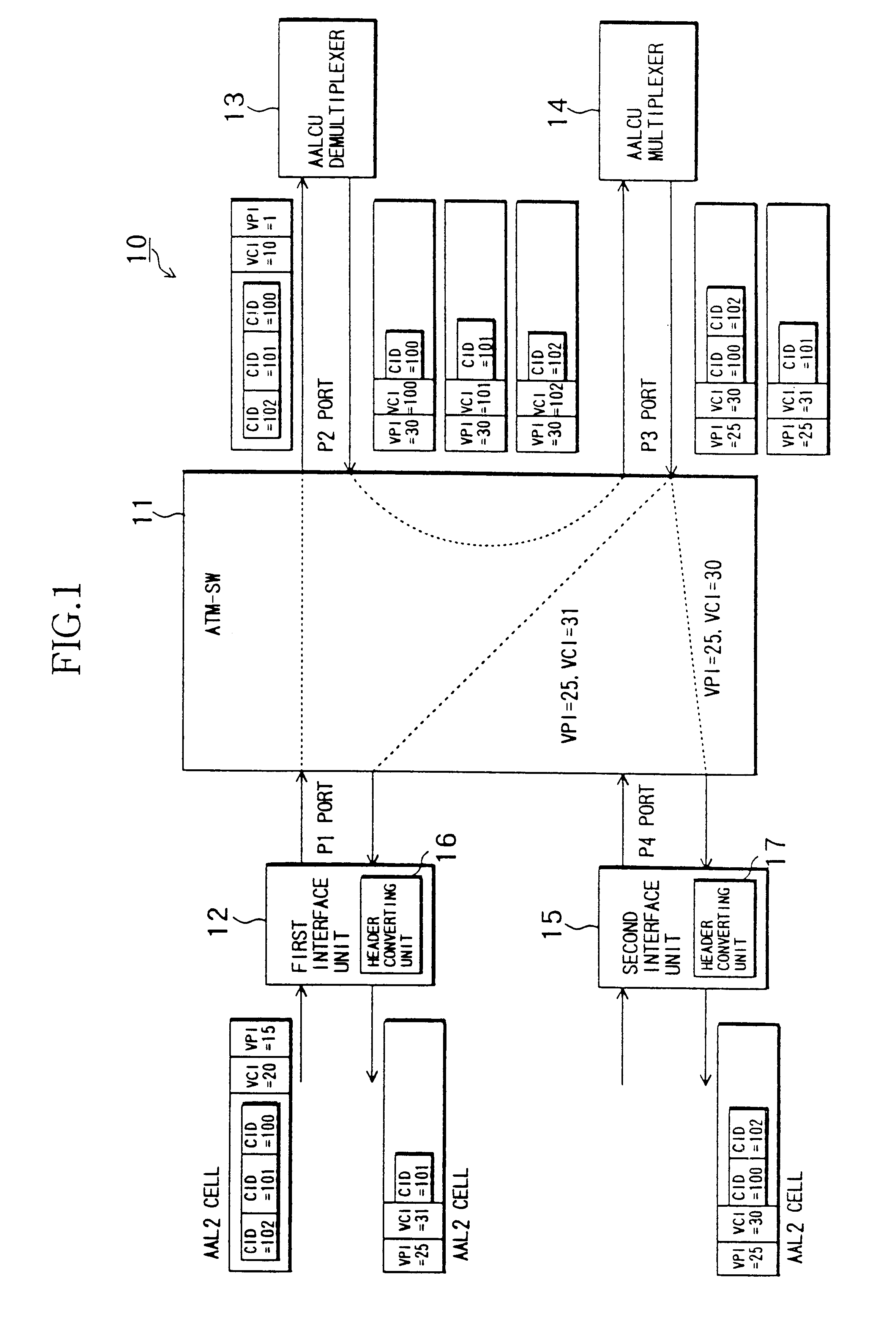
FIG. 2 is a diagramstructural drawing of an ATM switching apparatus 20 applicable to a short cell in accordance with the Embodiment 2 of the present invention. In the ATM switching apparatus 20, an arrangement for processing an AAL Type 1 format cell (hereinafter referred to as AAL 1 cell) is added to the ATM switching apparatus 10 of the Embodiment 1. The ATM switching apparatus 20 differs from the ATM switching apparatus 10 in the following points. Namely, an AAL2 cell (VPI=60, VCI=20) and an AAL 1 cell (VPI-70, VCI=20) are intermingly inputted to a first interface unit 21.

A header converting unit 23 of the first interface unit 21 converts the header of the AAL2 cell inputted to the first interface unit 21 into VPI=1, VCI=20. The header converting unit 23 converts the header of the AAL 1 cell into VPI=2, VCI=20. The first interface unit 21 outputs the cell processed by the header converting unit 23 to the ATM-SW 11.

When the cell outputted from the first interface unit 21 is inputt...

embodiment 3

FIG. 3 is a diagram showing an ATM switching apparatus 30 applicable to a short cell in accordance with a Embodiment 3 of the present invention. In FIG. 3, the ATM switching apparatus 30 has an ATM-SW 11, a first interface unit 12, and a second interface unit 15 in the ATM switching apparatus 10 of the Embodiment 1 (see FIG. 1). An AALCU multiplexing / demultiplexing apparatus (hereinafter referred to as multiplexer / demultiplexer) 31 is connected to a P2 port of the ATM-SW 11.

The following settings are applied to the ATM-SW 11. Namely, the ATM-SW 11 outputs a cell having VPI=20, VCI=20 and cells having VPI=30, VCIs=100 to 102 from the P2 port. In addition, the ATM-SW 11 outputs a cell having VPI=15, VCI=30 from a P1 port. Further, the ATM-SW 11 outputs a cell having VPI=16, VCI=31 from a P4 port.

An AAL2 cell (VPI=20, VCI=20) storing a plurality of short cells is inputted to the first interface unit 12. However, a header converting unit 16 converts the VPI / VCI of the AAL2 cell (VPI=20,...


PUM


Abstract

An ATM switching apparatus applicable to a short cell including an ATM-SW outputting a cell from an output path corresponding to a cell identifier, an interface unit, a demultiplexer, and a multiplexer. The interface unit sets, when a cell storing a plurality of short cells is inputted, the cell identifier so that the cell is transmitted from ATM-SW to the demultiplexer, and outputs the cell toward the ATM-SW. The demultiplexer receives the cell and produces a plurality of partial fill cells, and outputs them, while setting an identifier of each partial fill cell, the partial fill cell is outputted. The multiplexer receives a plurality of the partial fill cells, produces a cell storing a plurality of the short cells in accordance with the identifiers and outputs the cell to the ATM-SW.

Description

1. Field of the InventionThe present invention relates to an asynchronous transfer mode (ATM) switching apparatus applicable to a short cell suitable for transferring low-bit rate information.2. Description of Related ArtUpon carrying out communications by the ATM, data is loaded in a payload which is called an ATM cell which is a unit of data switching. The ATM cell is transmitted throuh an ATM connection setting previously. The ATM cell, when transmitted within the ATM network, is allocated with one destination information (virtual path identifier / virtual channel identifier (VPI / VCI)) per ATM connection. The VPI / VCI are loaded in the header of the ATM cell. The ATM cell is transmitted through the ATM connection corresponding to the VPI / VCI.In the technical field relating to mobile communication, data is converted into a compressed low-bit rate data format for its transmission so that a communication band may effectively be used. If the low-speed bit rate information is loaded a pa...

Claims


Application Information

Patent Timeline
Patent Type & Authority Patents(United States)
IPC IPC(8): H04Q11/04H04L12/56H04L47/43H04Q3/00
CPCH04L12/5601H04L49/3081H04Q11/0478H04L2012/5628H04L2012/5653H04L2012/5656H04L2012/5661H04L2012/5672
Inventor ONO, HIDEAKITAKECHI, RYUICHIFUJISAWA, TORU
Owner FUJITSU LTD
Why Eureka
Try Eureka