
Switching system for telecommunication networks

a technology of telecommunication network and switching system, applied in data switching network, frequency-division multiplex, instruments, etc., can solve the problems of crossbar switch square growth of complexity, different input-output pairs of crossbar switch may have different transit delays,

Inactive Publication Date: 2008-02-26
SPRINT CORPORATION
View PDF11 Cites 5 Cited by
  • Summary
  • Abstract
  • Description
  • Claims
  • Application Information

AI Technical Summary

Problems solved by technology

First and foremost, crossbar switches have a square growth of complexity.
As a result, they do not scale well to large sizes.
Additionally, different input-output pairs of a crossbar switch may have different transit delays.
As a result, a fairness problem arises when the crossbar switch is operated in a self-routing mode.
Finally, despite being non-blocking, crossbar switches suffer from output blocking.
As a result, buffers are oftentimes necessary to reduce cell losses in ATM switching systems based upon crossbar switch technology.
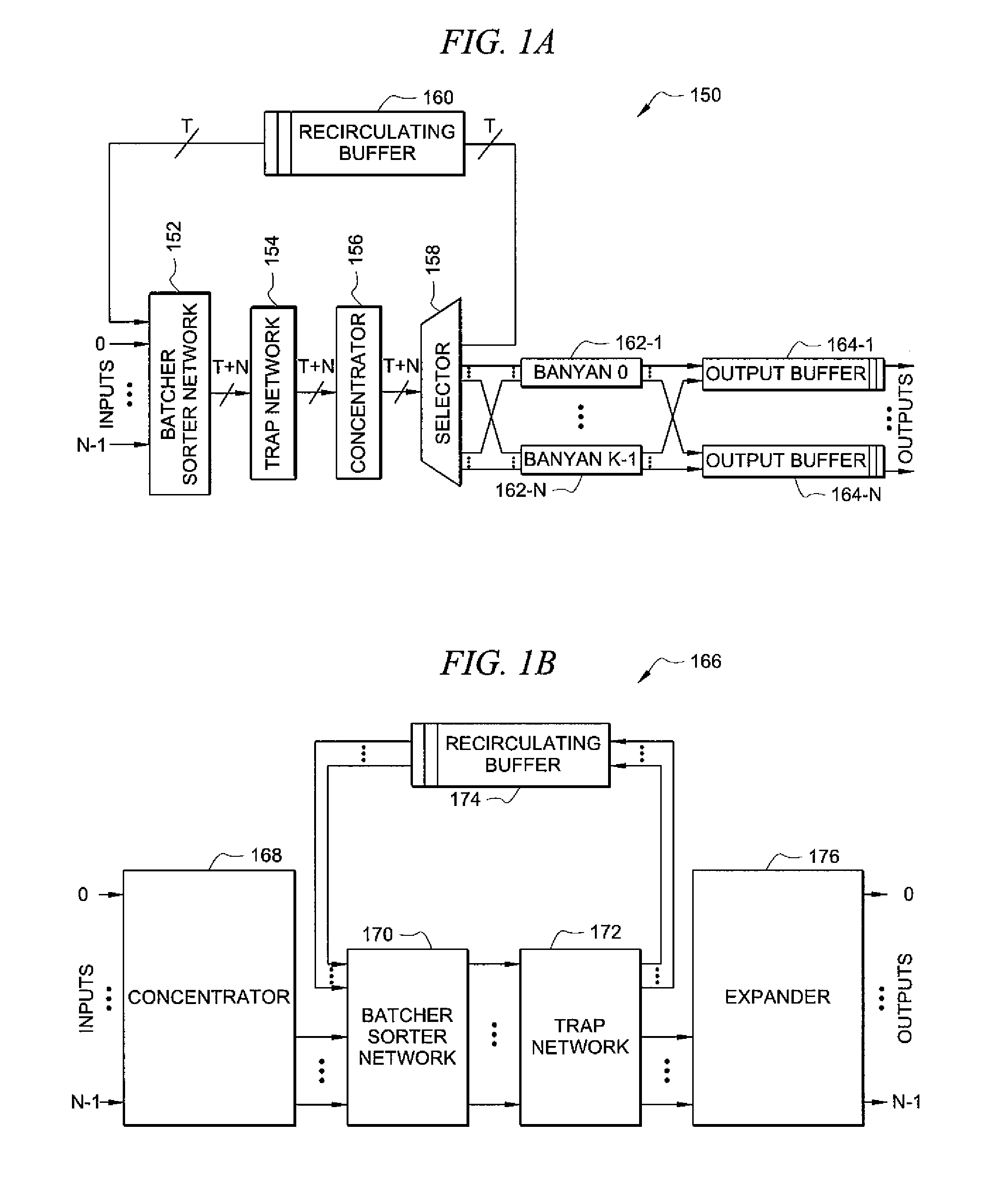
However, while the Banyan network's path-uniqueness characteristic preserves cell sequencing in Banyan network-based switching systems, it results in the switching systems being internally blocking.
Thus, while the Banyan network-based switching systems and the crossbar switch-based switching systems both suffer from degraded performance when the size of the switching system is increased, the degradation is more significant for the Banyan network-based switching systems because the crossbar switching system suffers only from output blocking while the Banyan network-based switching system suffers from both output blocking and an internal blocking which increases in severity with the number of stages therein.
Finally, because the ATM switching system 150 cannot be readily partitioned into integrated circuits, its commercial applicability is relatively limited.

Method used


Image

  • Switching system for telecommunication networks
  • Switching system for telecommunication networks
  • Switching system for telecommunication networks

Examples


Embodiment Construction

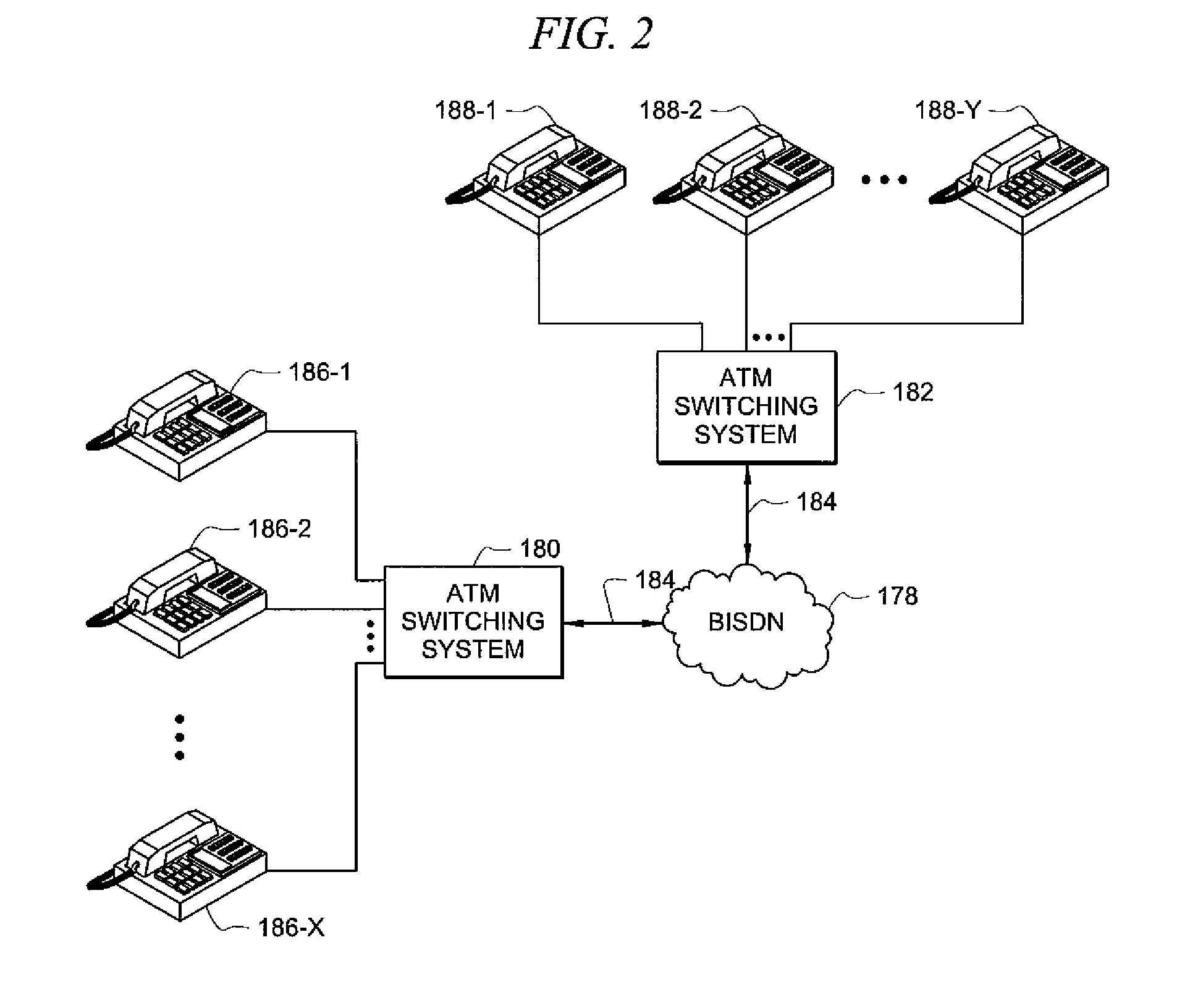
[0021]Referring now to FIG. 2, a telecommunications network 178 incorporating a switching system 180 constructed in accordance with the teachings of the present invention will now be described in greater detail. As disclosed herein, the telecommunications network 178 is a broadband integrated data services network (“BIDSN”), a telecommunications network having a network architecture which utilizes asynchronous transfer mode (“ATM”) as its communication protocol. Of course, the present disclosure of the telecommunications network 178 as a BIDSN is purely by way of example and it is fully contemplated that the telecommunications network may be any broadband or other telecommunication network utilizing the ATM communication protocol. For example, the telecommunication network may be a private ATM network. Furthermore, the ATM telecommunication network may be configured as either a connection-oriented network service (“CONS”) packet switched network or a connectionless network service (...


PUM


Abstract

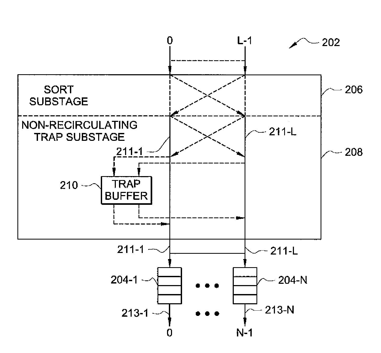
The present invention is directed to a high performance broadband ATM switching system comprised of concentrator, non-recirculating sort-trap and queuing stages. The concentrator stage concentrates cells entering the switch by discarding idle inputs thereto. Cells arriving at the non-recirculating sort-trap stage during a time slot are sorted based upon destination address and priority. Cells having a unique address for the time slot are placed in a corresponding output queue while cells having non-unique destination addresses are re-routed to a trap buffer which ages the cell until a subsequent time slot in which the destination address is unique.

Description

CROSS-REFERENCE TO RELATED APPLICATIONS[0001]Not applicable.STATEMENT REGARDING FEDERALLY SPONSORED RESEARCH OR DEVELOPMENT[0002]Not applicable.REFERENCE TO A MICROFICHE APPENDIX[0003]Not applicable.FIELD OF THE INVENTION[0004]The invention is directed to a switching system for telecommunication networks. The switching system achieves enhanced throughput by incorporating a three-stage, non-recirculating configuration thereinto.BACKGROUND OF THE INVENTION [0005]Over the years, switching systems having a wide variety of architectures have been developed for use in telecommunication networks. A “crossbar” switch is a single-stage, single-path, non-blocking switch. Broadly speaking, an N by N crossbar switch consists of a square array of N2 individually operated crosspoints, one for each input-output pair, having two possible states—cross (default) and bar. For such an N by N crossbar switch, a connection between input port i and output port j is established by setting the (i, j) crossp...

Claims


Application Information

Patent Timeline
IPC IPC(8): H04L12/56
CPCH04L12/5601H04L49/1561H04L49/105H04L2012/5651H04L2012/5681H04L2012/5642
Inventor KHANKHEL, SAEEDA
Owner SPRINT CORPORATION
Learn More