Exhaust gas cleaning system having particulate filter

a technology of exhaust gas and filter, which is applied in the direction of exhaust treatment electric control, electrical control, separation process, etc., can solve the problems of reducing the efficiency of the engine, generating errors, and affecting the timing of regeneration

Inactive Publication Date: 2004-07-06
DENSO CORP
View PDF12 Cites 76 Cited by
  • Summary
  • Abstract
  • Description
  • Claims
  • Application Information

AI Technical Summary

Problems solved by technology

Otherwise, the timing of the normal fuel injection is retarded to decrease efficiency of the engine.
Since the data of the map are obtained in a steady operating state, an error will be generated if the map is used in a transitional state.
Therefore, the errors are accumulated, and timing of the regeneration may become erroneous.
However, the pressure difference is small if the flow rate of the exhaust gas passing through the particulate filter is small.
Therefore, the collection quantity of the particulate matters cannot be necessarily measured with adequate accuracy.
Moreover, a steady pressure difference cannot be obtained in the transitional state.
As a result, the measuring accuracy may be deteriorated.
In the second example, a great error may be generated in some operating conditions because the present collection quantity is calculated based on the passing state of the exhaust gas at the particulate filter at the time when the present collection quantity is calculated.

Method used


Image

  • Exhaust gas cleaning system having particulate filter
  • Exhaust gas cleaning system having particulate filter
  • Exhaust gas cleaning system having particulate filter

Examples


first embodiment

(First Embodiment)

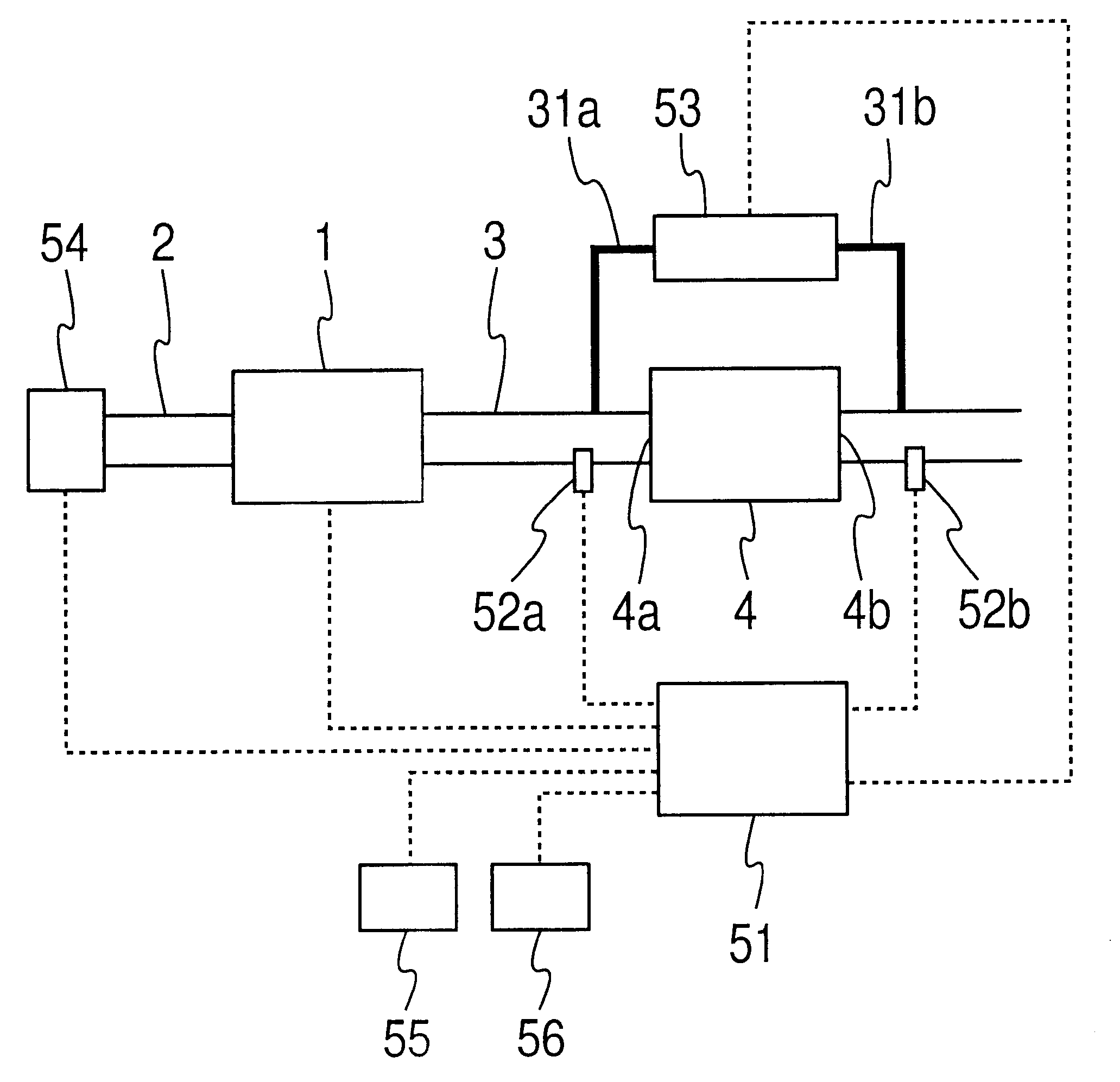
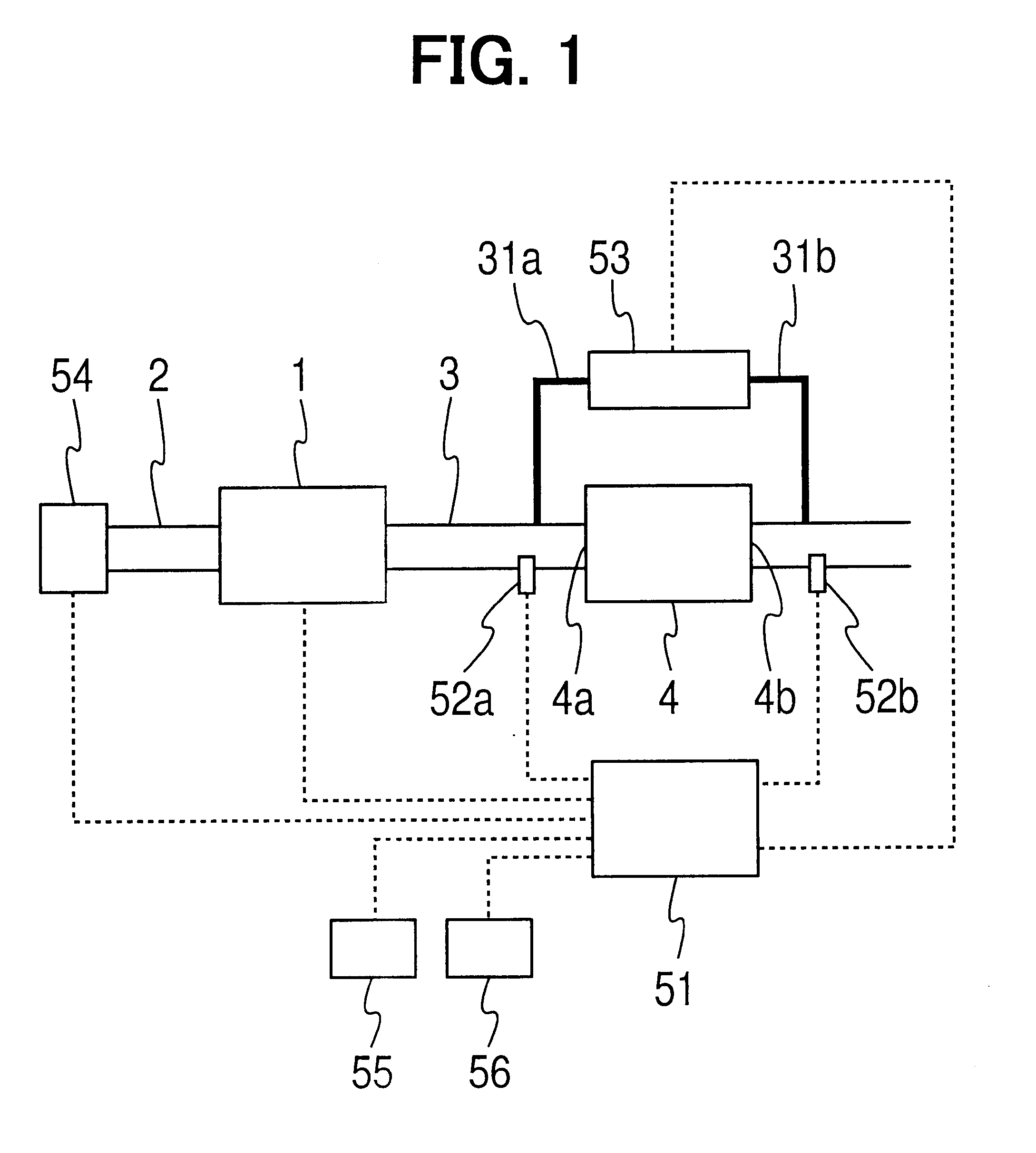
Referring to FIG. 1, a diesel engine having an exhaust gas cleaning system according to the first embodiment is illustrated. An engine main body 1 is connected with an intake passage 2, through which intake air passes, and with an exhaust passage 3, through which exhaust gas passes. A diesel particulate filter (DPF) 4 is disposed in the exhaust passage 3. A filter main body of the DPF 4 is a honeycomb made of a porous ceramics such as cordierite or silicon carbide. An inlet or an outlet of each passage of the honeycomb body is blocked. The exhaust gas discharged from the respective cylinders of the engine main body 1 enters the DPF 4 through an inlet 4a of the DPF 4 and passes through porous filter walls, then, flows downstream through an outlet 4b of the DPF 4. At that time, exhaust particulate matters included in the exhaust gas are collected by the DPF 4, and deposit in the DPF 4. An oxidization catalyst, whose main component is a noble metal such as platinum or...

second embodiment

(Second Embodiment)

In FIG. 6, an internal combustion engine having an exhaust gas cleaning system according to the second embodiment is illustrated.

A pressure sensor 53A is disposed just upstream of the DPF 4 for measuring the pressure of the exhaust gas passing through the exhaust pipe 3 at the point. An ECU 51A stores a map of a relation between the exhaust gas pressure just upstream of the DPF 4 and the PM collection quantity. Thus, the PM collection quantity is provided in accordance with the pressure measured by the pressure sensor 53A. The ECU 51A calculates the PM collection quantity based on the pressure measured by the pressure sensor 53A during the measuring accuracy is high.

The pressure just downstream of the DPF 4 is a sum of the atmospheric pressure and the pressure loss at the catalyst or the muffler downstream of the DPF 4. Therefore, the pressure just downstream of the DPF 4 can be considered constant in the case where certain measuring accuracy is required. Therefor...


PUM

PropertyMeasurementUnit
temperatureaaaaaaaaaa
thresholdaaaaaaaaaa
concentrationaaaaaaaaaa

Abstract

In an exhaust gas cleaning system of an internal combustion engine having a diesel particulate filter (DPF), measuring accuracy of a collection quantity of particulate matters collected by the DPF is estimated based on an accelerator position change rate and an exhaust gas flow rate. When the measuring accuracy is high, the collection quantity is calculated based on a pressure difference and the exhaust gas flow rate at the DPF. If the measuring accuracy is low, an increment value of the collection quantity is calculated based on a quantity of the particulate matters discharged from an engine main body. Then, the collection quantity is calculated by adding the collection quantity increment value to the previous collection quantity calculated based on the pressure difference and the exhaust gas flow rate while the measuring accuracy is high.

Description

This application is based on and incorporates herein by reference Japanese Patent Application No. 2002-174553 filed on Jun. 14, 2002.1. Field of the InventionThe present invention relates to an exhaust gas cleaning system for an internal combustion engine, in particular, to a method of regenerating a particulate filter.2. Description of Related ArtLately, improvement in exhaust emission of an internal combustion engine mounted on a vehicle and the like is required. Specifically, exhaust particulate matters such as soot or a soluble organic fraction included in the exhaust gas discharged from a compression-ignition type diesel engine running on diesel oil should be removed, as well as carbon oxide, hydrocarbon and nitrogen oxide. Therefore, a particulate filter made of a porous material is disposed in an exhaust passage of the diesel engine for collecting the exhaust particulate matters included in the exhaust gas.When the exhaust gas passes through porous filter walls of the particu...

Claims


Application Information

Patent Timeline
Patent Type & Authority Patents(United States)
IPC IPC(8): F01N11/00F01N3/023F01N9/00F02D41/02F01N3/035F02D45/00B01D46/42B01D46/44F01N3/02F01N3/20F02D41/14
CPCF01N3/023F01N3/035F01N9/002F01N11/002F02D41/029F02D41/1445F02D41/1448F01N2430/085F01N2900/0421F01N2900/0422F02D41/187F02D2200/0404F02D2200/0812Y02T10/47Y02T10/40
Inventor KUBOSHIMA, TSUKASAOKUGAWA, SHINICHIROSAITO, MAKOTOYAHATA, SHIGETOKINUGAWA, MASUMI
Owner DENSO CORP
Why Eureka
Try Eureka