Flushing mechanism for a dual flush cistern

a technology of flushing mechanism and cistern, which is applied in the direction of flushing devices, water installations, constructions, etc., can solve problems such as complex structur

Inactive Publication Date: 2004-09-07
CISTERN TECH PTE
View PDF5 Cites 43 Cited by
  • Summary
  • Abstract
  • Description
  • Claims
  • Application Information

AI Technical Summary

Problems solved by technology

The majority of the prior art mechanisms include a large number of moving parts and are complicated in their structure in that various non-linear motions are involved in operation of the valve.

Method used


Image

  • Flushing mechanism for a dual flush cistern
  • Flushing mechanism for a dual flush cistern
  • Flushing mechanism for a dual flush cistern

Examples


Embodiment Construction

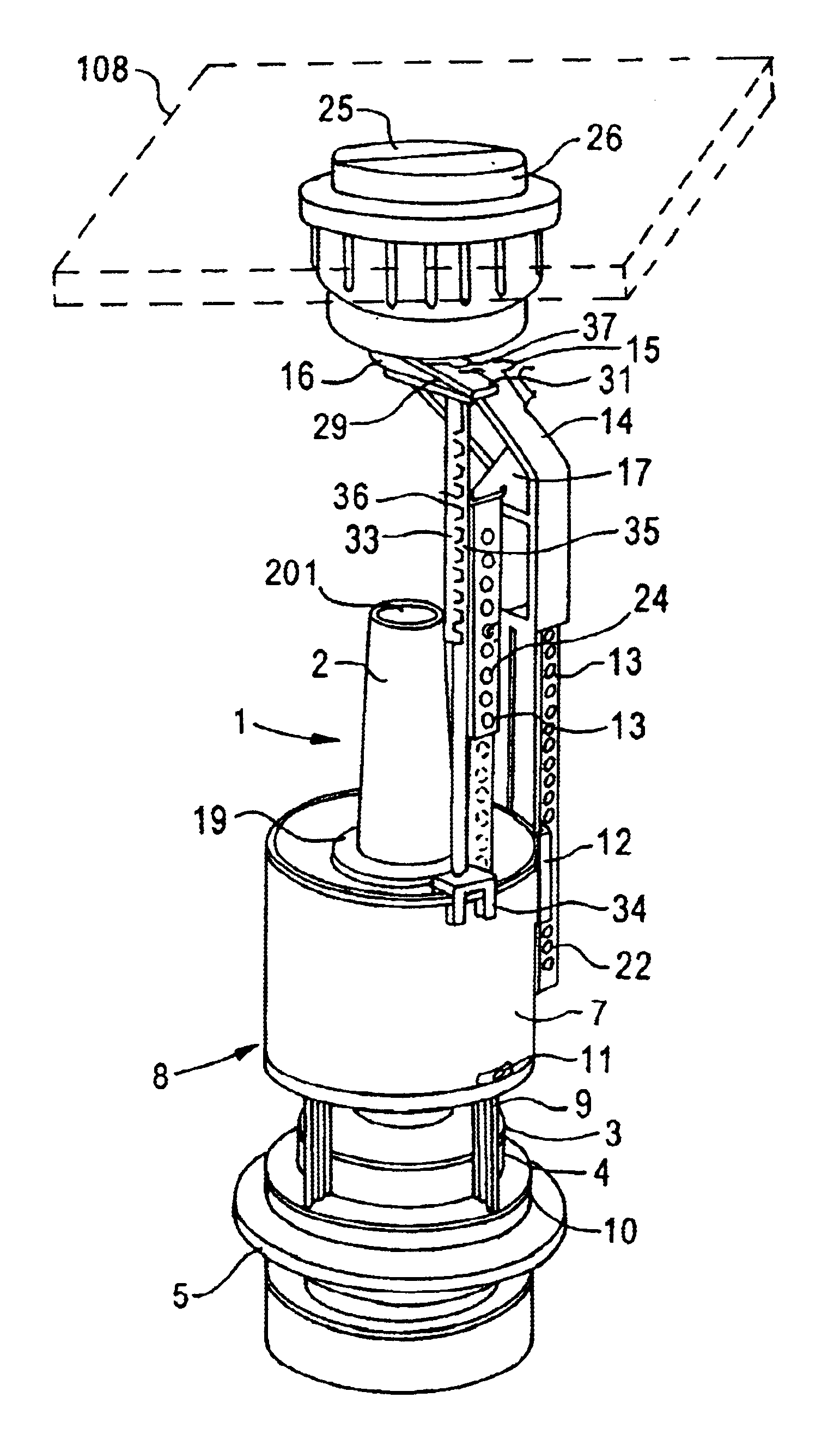
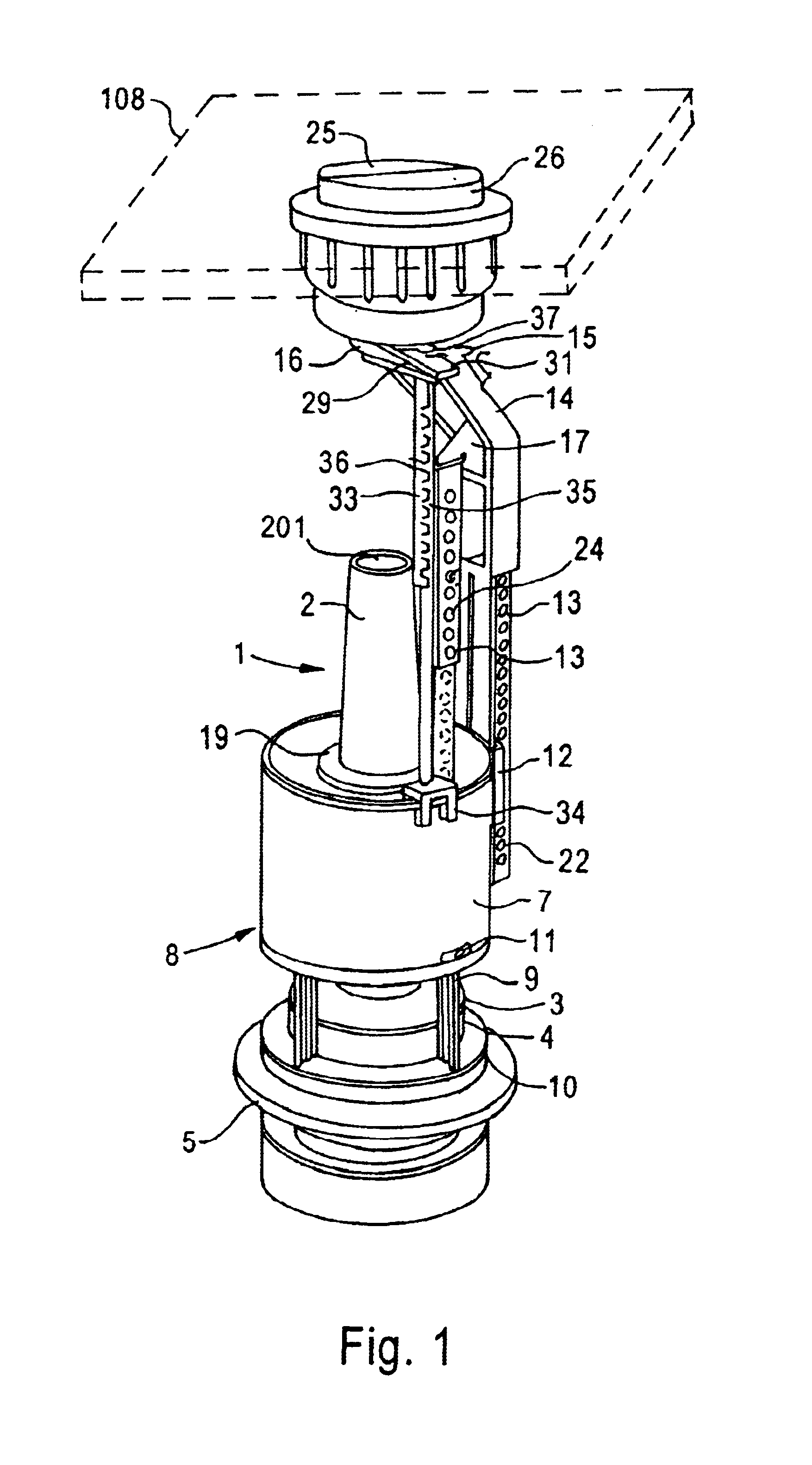
The invention will now be described in greater detail by way of example with reference to the drawings, in which:

FIG. 1 is an isometric view of one form of flushing mechanism according to the invention in the closed position of the valve;

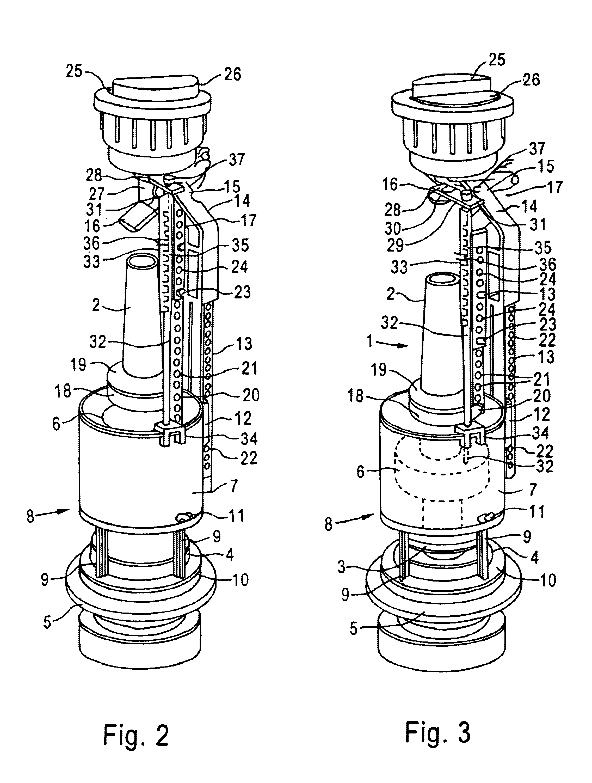
FIG. 2 is an isometric view of the valve mechanism of FIG. 1 in the full flush position;

FIG. 3 is an isometric view of the mechanism of FIG. 1 in the partial flush position;

FIG. 4 is a section through the mechanism of FIG. 1 in the full flush position but with the stop rod not shown; and

FIG. 5 is a view as in FIG. 4 in the partial flush position.

As shown in the drawings, the flushing mechanism comprises a float assembly indicated generally by reference numeral 1 which comprises a valve stem 2 which is hollow and open at both ends (only one of which is visible at 201 in FIG. 1) and carries towards one end a valve closure member 3 which seats on a valve seat 4 on a fixture member 5 by which the float assembly 1 is mounted to the outlet (not shown) of ...


PUM


Abstract

A flushing mechanism for a dual flush cistern system comprises a float assembly (1) comprising a hollow valve stemn (2) carrying a sealing valve (3) for sealing the outlet opening of the cistern at or towards one end and being open at each end to define an overflow passage and a float (6) fixedly attached around the valve stem (2), a cylindrical guide member (7) surrounding the float (6) and having at the end adjacent the sealing valve at least one opening to allow liquid to pass to the outlet opening, an operating rod (17) arranged to move vertically upward to raise the float assembly (1) to open the vavle (3), first and second operating means (25, 26) arranged to effect such vertical movement of the operating rod (17), the first operating means (25), an operation, being arranged to raise the float assembly (1) a first distance to a level which the float assembly (1) is buoyant, and the second operating means (26) being arranged to raise the float assembly (1) a second distance, less than the first distance in a level at which the float assembly (1) is not buoyant, whereby when the first operating means (25) is operated and released, a first predetermined quantity of liquid flows from the cistern, and when the second operating means (26) is operated and released a second, smaller, predetermined quantity of liquid flows from the cistern.

Description

BACKGROUND TO THE INVENTIONIn recent years it has, in many countries, been a requirement that all new toilet cisterns installed should have a dual-flush function, in which a full flush releasing a large quantity of flushing liquid can be used when solid waste is to disposed of and a partial flush releasing a smaller quantity of flushing liquid can be used when a full flush is not required, for example, when liquid waste is to be disposed of.Many such mechanisms for dual flush cisterns have been proposed.In certain systems the cistern is divided into two parts by a weir having a movable gate such that when a partial flush is required the gate remains closed and only the liquid on one side of the weir is released through the cistern outlet but when a full flush is required the gate is opened allowing liquid on both sides of the weir to pass through the outlet. Examples of such dual flush mechanisms are disclosed in AU-B-56165 / 80 and WO93 / 15284.Another type of dual flushing mechanism r...

Claims


Application Information

Patent Timeline
Patent Type & Authority Patents(United States)
IPC IPC(8): E03D1/02E03D1/14
CPCE03D1/142
Inventor HO, KING CHEE
Owner CISTERN TECH PTE
Why Eureka
Try Eureka