Stacked-type evaporator

a stacking type, evaporator technology, applied in indirect heat exchangers, laminated elements, lighting and heating apparatus, etc., can solve the problem of evaporator 1 being large in siz

Inactive Publication Date: 2004-11-09
CALSONIC KANSEI CORP
View PDF10 Cites 12 Cited by
  • Summary
  • Abstract
  • Description
  • Claims
  • Application Information

AI Technical Summary

Problems solved by technology

This arrangement, however, causes the evaporator 1 to become large in size, so that it is not preferable.

Method used


Image

  • Stacked-type evaporator
  • Stacked-type evaporator
  • Stacked-type evaporator

Examples


Embodiment Construction

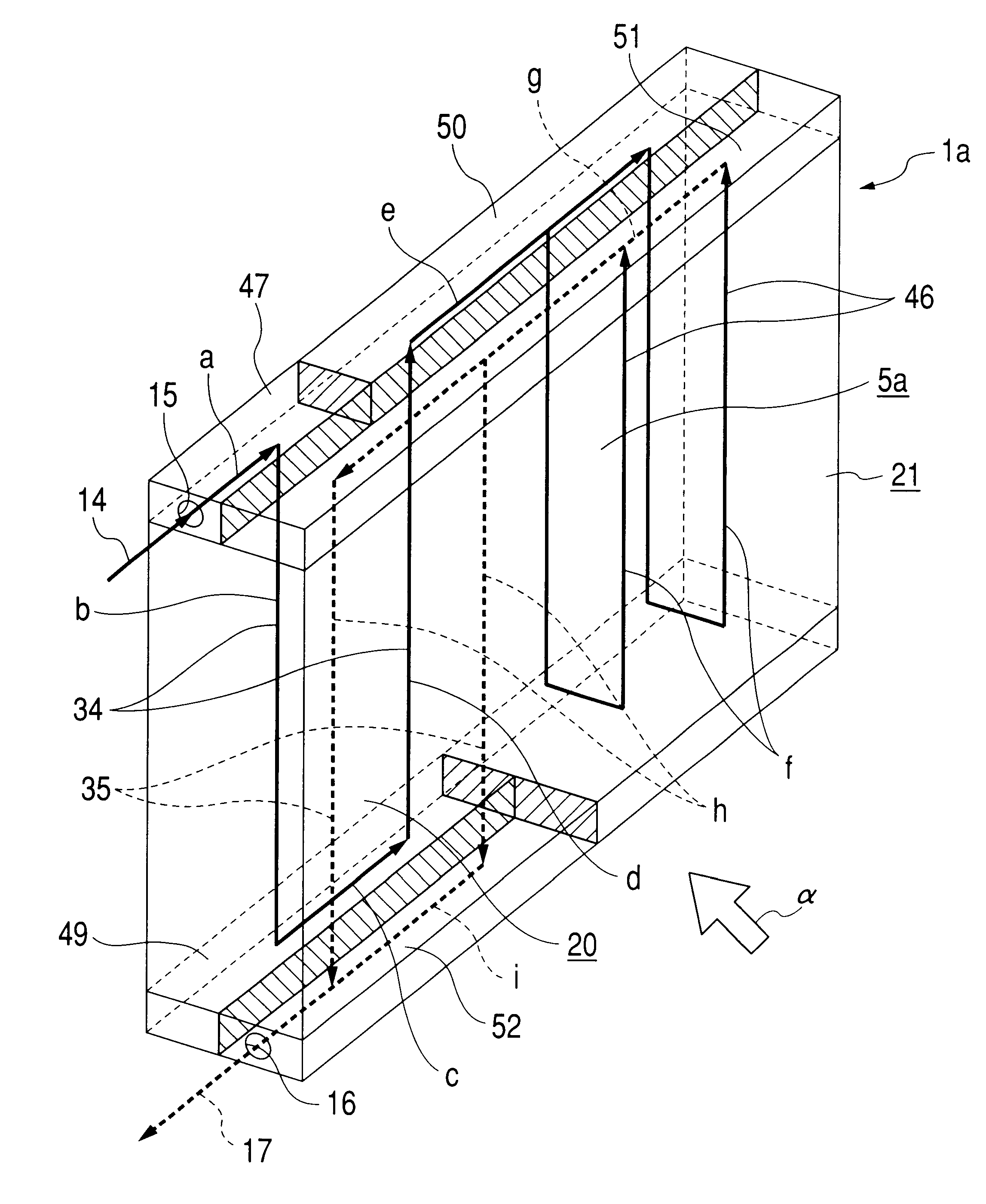
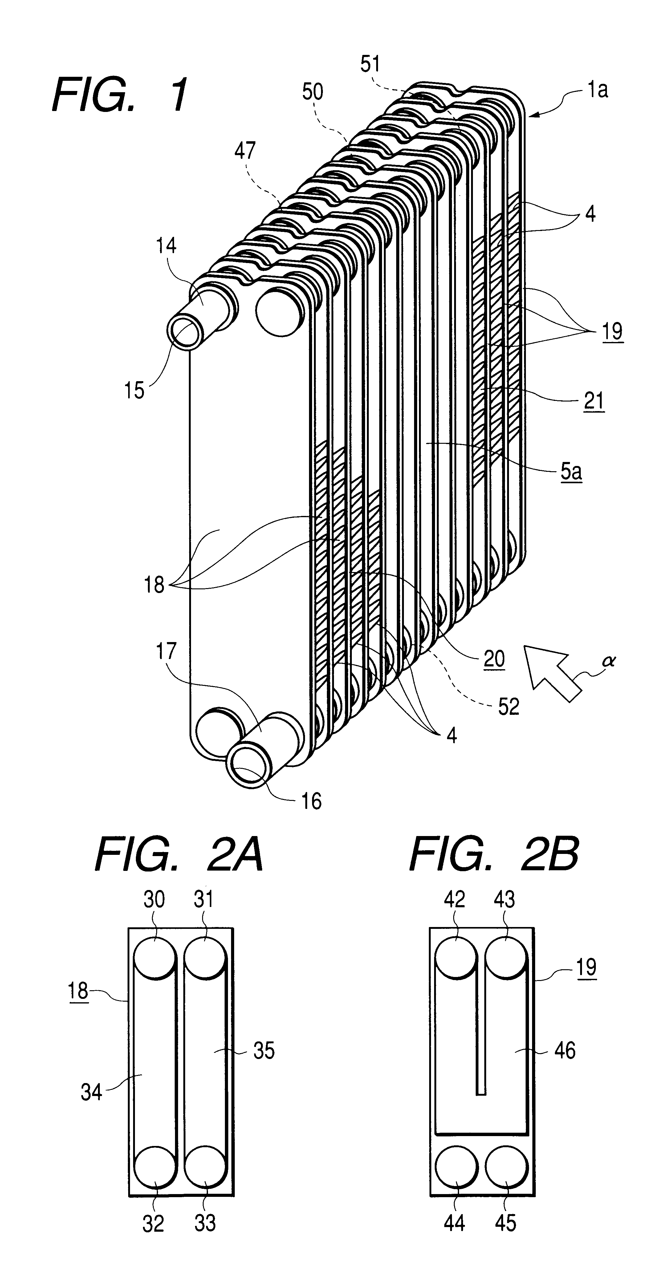
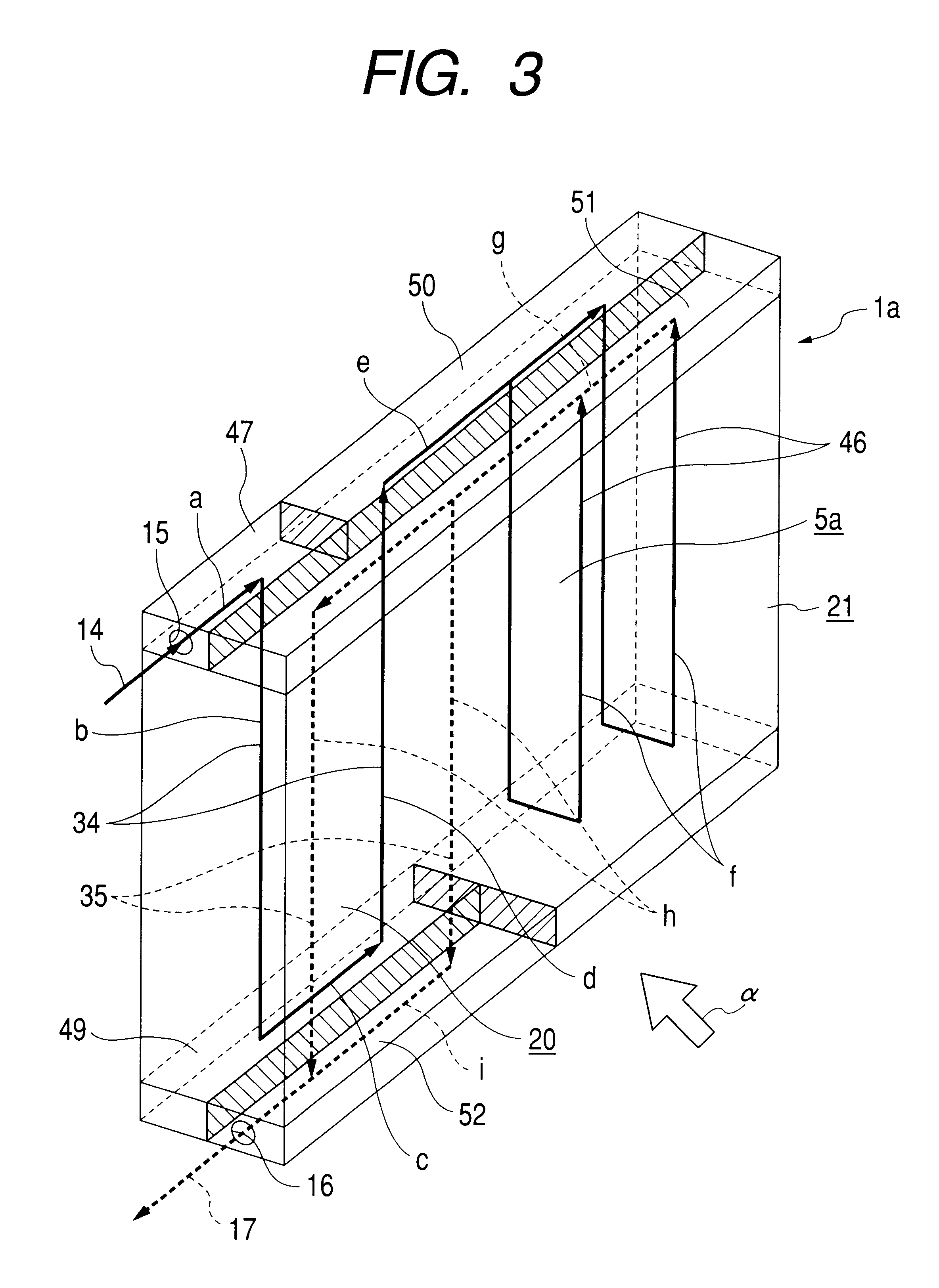
FIGS. 1 to 6 illustrate an embodiment of the invention. An evaporator 1a of the invention has a core section 5a which is formed by stacking a plurality of first elements 18, a plurality of second elements 19, and a plurality of corrugated-type fins 4. A widthwise one half portion (a left half portion in FIGS. 1, 3, and 6) of the core section 5a is constituted by a first section 20 formed by stacking the plurality of first elements 18 in a state in which the fins 4 are provided between adjacent ones of the first elements 18. Similarly, a widthwise other half portion (a right half portion in FIGS. 1, 3, and 6) of the core section 5a is constituted by a second section 21 formed by stacking the plurality of second elements 19 in a state in which the fins 4 are provided between adjacent ones of the second elements 19. In addition, the first elements 18 and the second elements 19 are fabricated such that two first metal plates 22 and two second metal plates 23 having recessed portions on ...


PUM


Abstract

A widthwise one half portion of a core section 5a is constituted by a first section 20 formed by stacking a plurality of first elements having first and second linear channels 34 and 35 inside them and fins, and a widthwise other half portion thereof is similarly constituted by a second section 21 formed by stacking a plurality of second elements respectively having U-shaped channels 46 inside them and fins. The number of times the refrigerant fed into a thicknesswise one half portion on an inlet tank 47 side of the first section 20 is turned back in an opposite direction concerning a longitudinal direction of the first linear channels 34 inside this thicknesswise one half portion is made more numerous than the number of times the refrigerant fed into a thicknesswise other half portion on an outlet tank 52 side of the first section 20 is turned back in the opposite direction concerning the longitudinal direction of the second linear channels 35 inside this thicknesswise other half portion.

Description

1. Field of the InventionThe present invention relates to a stacked-type evaporator incorporated in an air-conditioner, particularly an air-conditioner for an automobile to cool air for air-conditioning the air inside a vehicle compartment.2. Description of the Related ArtAn evaporator, for evaporating a refrigerant to cool the air flowing over it, is incorporated in an air-conditioner for an automobile. As such an evaporator incorporated in the air-conditioner for an automobile, a so-called stacked-type evaporator is conventionally known which is constructed by stacking together a plurality of metal plates, as known in JP-A-62-798, JP-A-7-12778U, and JP-A-9-318195. This stacked-type evaporator is constructed by stacking together a plurality of heat transfer tube elements each formed by combining two metal plates in the form of a peapod. FIGS. 8 and 9 show a stacked-type evaporator having the structure disclosed in JP-A-9-318195 mentioned above.This evaporator 1 is arranged such tha...

Claims


Application Information

Patent Timeline
Patent Type & Authority Patents(United States)
IPC IPC(8): F28F3/00F28F3/04F28D1/02F28D1/03F25B39/02F28F3/08
CPCF28D1/0333F28F3/04F28D1/0341F28D2021/0085
Inventor NARAHARA, MITSUNARISASAKI, YOSHIHIROKOJIMA, KAZUHIROASANUMA, TORUKOGA, YOSHIAKI
Owner CALSONIC KANSEI CORP
Why Eureka
Try Eureka