Remotely actuated multiple pressure direct acting relief valve

a relief valve and remote action technology, applied in the direction of valve operating means/releasing devices, functional valve types, transportation and packaging, etc., can solve the problem that trucking companies are limited in the use of their assets

Inactive Publication Date: 2005-01-04
GUYAN INT +1
View PDF9 Cites 23 Cited by
  • Summary
  • Abstract
  • Description
  • Claims
  • Application Information

AI Technical Summary

Benefits of technology

The present invention solves the problems associated with separate relief valves required for dump trailer and live floor trailer applications, and other problems by providing a multiple pressure direct acting relief valve comprising an actuating cylinder, a relief valve and an adjustment screw interconnecting the actuating cylinder and the relief valve. The relief valve includes a low pressure spring which biases a poppet valve arrangement permitting the poppet valve arrangement to be actuatable at a first predetermined pressure, such as 2,000 psi. The actuating cylinder includes a piston that is biased by a high pressure spring causing an additional compressive force to be applied to the poppet valve arrangement through an actuator rod received within the adjustment screw. In this manner, when pressure is applied to the piston within the actuating c

Problems solved by technology

From the foregoing, it is obvious that trucking companies encounter a problem when they operate both dump trailers and live floor trailers since different operating pressures and thus, separate relief valves are required for each application.
A t

Method used


Image

  • Remotely actuated multiple pressure direct acting relief valve
  • Remotely actuated multiple pressure direct acting relief valve
  • Remotely actuated multiple pressure direct acting relief valve

Examples


Embodiment Construction

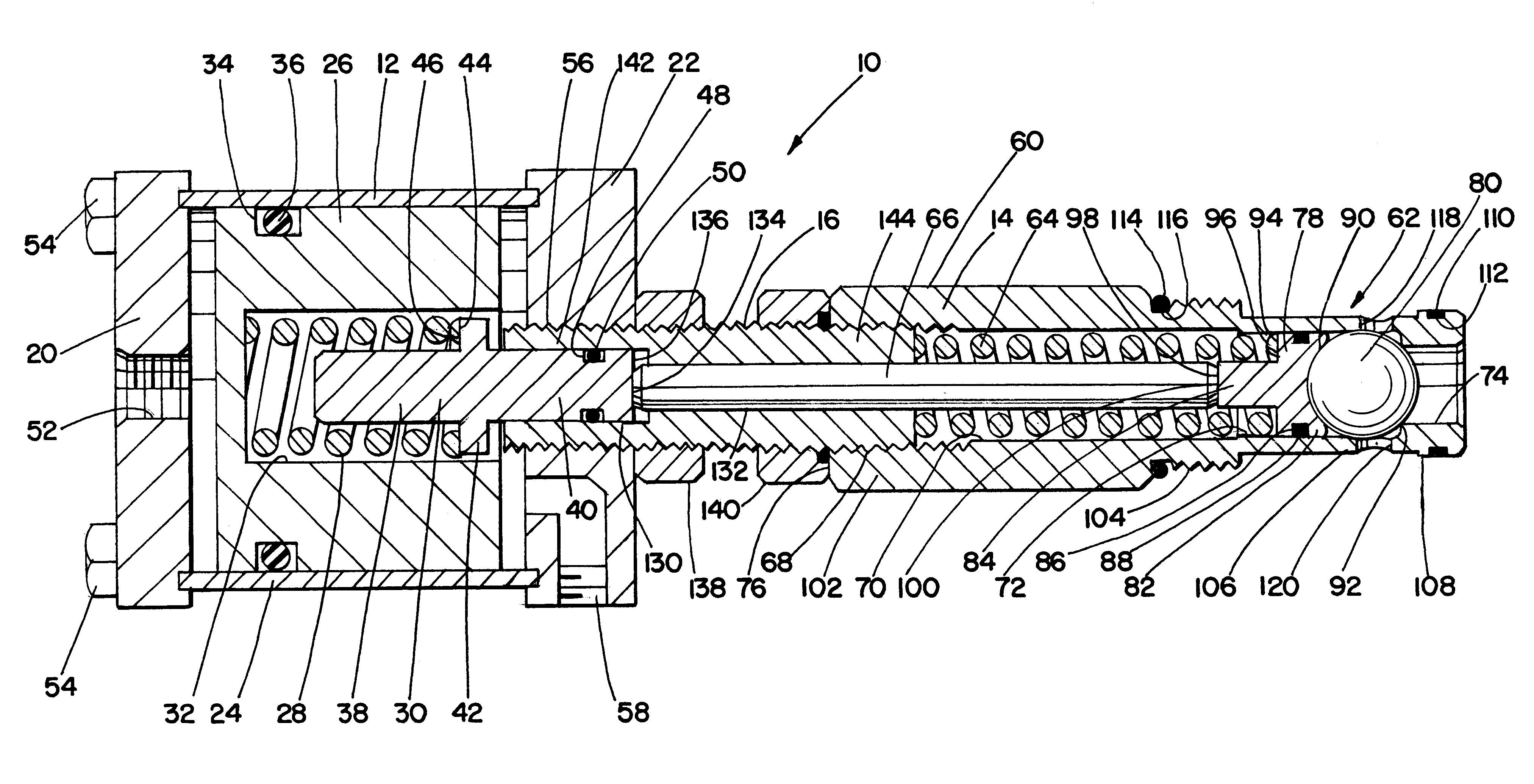
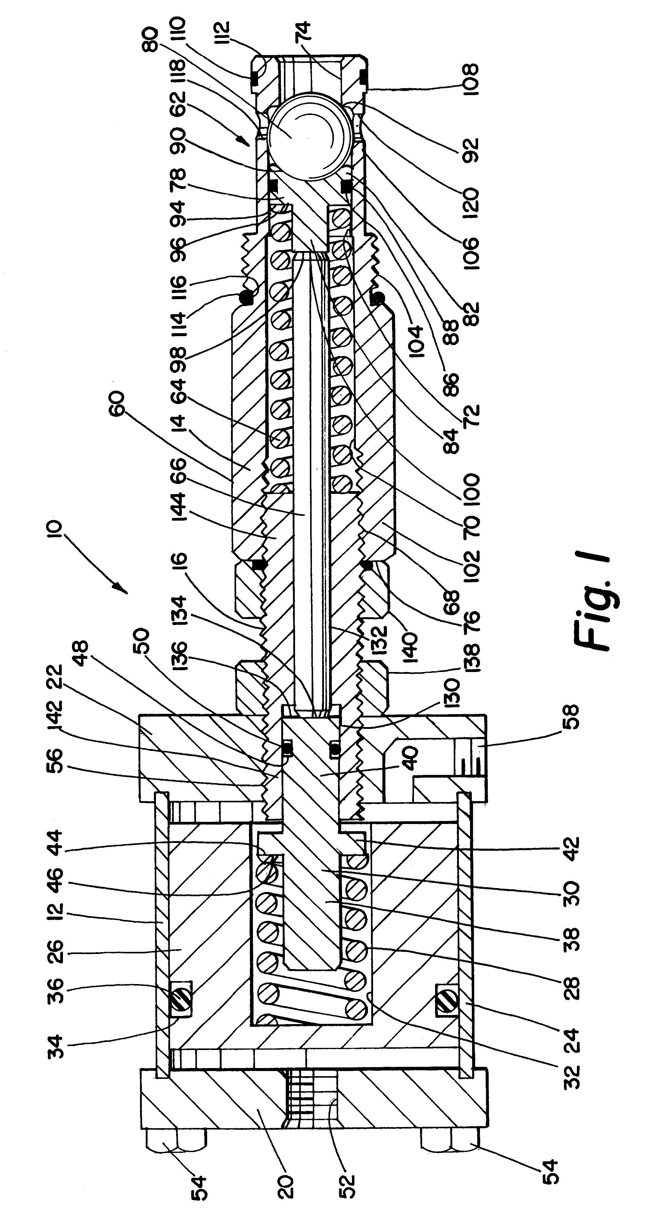
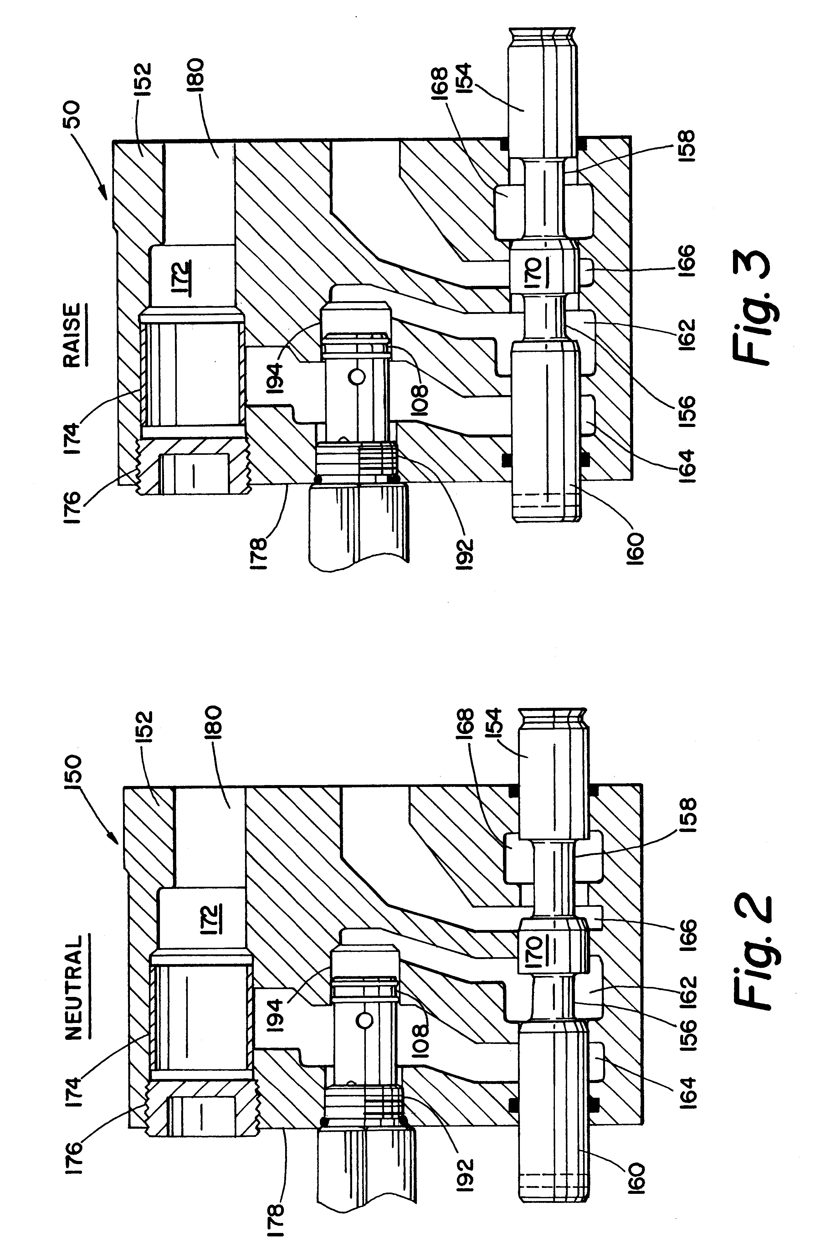
Referring now to the drawings where the illustrations are for the purpose of describing the preferred embodiment of the present invention and are not intended to limit the invention described herein, FIG. 1 is a cross-sectional view of the multiple pressure direct acting relief valve 10 of the present invention. The multiple pressure relief valve 10 is comprised of an actuating cylinder 12, a relief valve 14 and an adjustment screw 16 interconnecting the actuating cylinder 12 and the relief valve 14.

The actuating cylinder 12 is comprised of oppositely disposed end plates 20, 22, a sleeve member 24 disposed between end plates 20, 22, a piston 26 received within sleeve member 24, a high pressure spring 28 and a spring guide 30. Piston 26 has a blind bore 32 therein sized so as to receive high pressure spring 28. A circumferential recess 34 is provided in the body of piston 26 to receive an O-ring 36. Spring guide 30 is comprised of a first reduced diameter portion 38, a second reduced...


PUM


Abstract

A multiple pressure direct acting relief valve is disclosed. The multiple pressure relief valve comprises an actuating cylinder, a relief valve and an adjustment screw interconnecting the actuating cylinder and the relief valve. The relief valve includes a low pressure spring which biases a poppet valve arrangement permitting the poppet valve arrangement to be actuatable at a first pre-determined pressure. The actuating cylinder includes a piston that is biased by a high pressure spring causing an additional compressive force to be applied to the poppet valve arrangement through an actuating rod received through the adjustment screw. When pressure is applied to the piston within the actuating cylinder, an additional compressive force is applied by the high pressure spring and the actuator rod to the poppet valve arrangement causing the poppet valve arrangement to be actuatable at a second pre-determined pressure. Lock nuts are provided on the adjustment screw that interconnects the actuating cylinder and the relief valve. When the lock nuts are disengaged, the position of the adjustment screw can be moved relative to the actuating cylinder and the relief valve permitting the adjustment of both pre-determined actuating pressures for the poppet valve arrangement.

Description

TECHNICAL FIELDThe present invention relates, in general, to a remotely actuated relief valve, and, more particularly, to a remotely actuated relief valve that has two adjustable predetermined actuating pressures.BACKGROUND ARTTrucking companies typically operate both dump trailers and live floor trailers. Dump trailers utilize single acting single rod end telescopic cylinders that extend to raise the dump body and then retract to return the dump body to its transit position. The hydraulic system for dump trailers has a directional control valve integrated into the port end cover of the hydraulic pump used to actuate the telescopic cylinders. When the dump body is in the raise position, pump flow to the tank is blocked and the flow is directed through the load check valve to the hydraulic cylinder. In the neutral position, pump flow to the tank is allowed while the load check valve locks the hydraulic cylinder. When the dump body is in the lower position, both the pump flow and the ...

Claims


Application Information

Patent Timeline
IPC IPC(8): F16K17/06
CPCF16K17/065Y10T137/7905Y10T137/7929Y10T137/7928F16K15/044
Inventor FREDRICKSON, BRANT M.AUKERMAN, JOEL B.SMALLSREED, ALAN E.CONNER, RICHARD T.OLSZEWSKI, RICHARD A.
Owner GUYAN INT
Why Eureka
Try Eureka