
Two-component dispensing gun nozzle

a technology of dispensing gun and nozzle, which is applied in the direction of liquid transfer devices, combustion types, lighting and heating apparatus, etc., can solve the problems of static mixer clogging with polyurethane foam or froth formed in the mixer, dripping during gun operation, and limited nozzle design illustrated in the '204 paten

Inactive Publication Date: 2005-01-11
ICP CONSTR INC
View PDF25 Cites 40 Cited by
  • Summary
  • Abstract
  • Description
  • Claims
  • Application Information

AI Technical Summary

Benefits of technology

Accordingly, one of the major undertakings of the present invention is to provide an improved, nozzle for use with an airless two-component dispensing gun which can produce consistent spray patterns while the gun meters the foam over a wide flow range.
Still another object of the invention is an improved gun / nozzle configuration having an improved double seal protrusion / recess configuration for positively aligning and sealing the detachable nozzle to the gun body.

Problems solved by technology

The wall lessens but does not eliminate the risk of cross-over since the higher pressurized component must travel into the mixer and back to the lower pressure metering valve before cross-over can occur.
However, the nozzle design illustrated in the '204 patent may be limited because of the wall and nozzle inlet chamber tending to create turbulence for applications requiring very high flow rates.
Because the foam foaming reaction commences when the “A” and “B” components contact one another, it is clear that, once the gun is used, the static mixer will clog with polyurethane foam or froth formed within the mixer.
Nozzle drip conventionally means that a foam buildup occurs at the nozzle tip resulting in dripping during gun operation.
The nozzle is a throw away component and inevitably the foam components will react and produce foam in the nozzle, clogging the nozzle.

Method used


Image

  • Two-component dispensing gun nozzle
  • Two-component dispensing gun nozzle
  • Two-component dispensing gun nozzle

Examples


Embodiment Construction

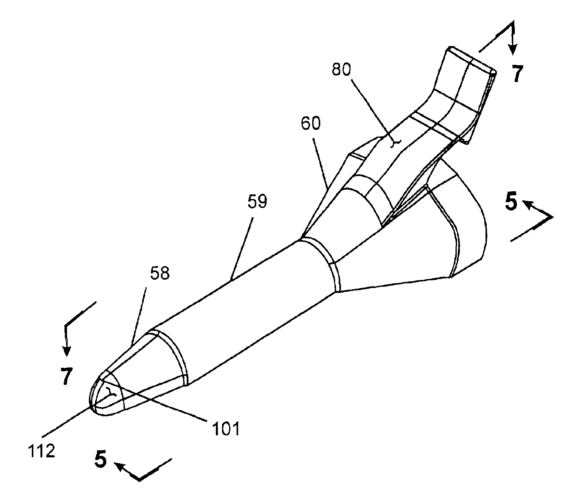
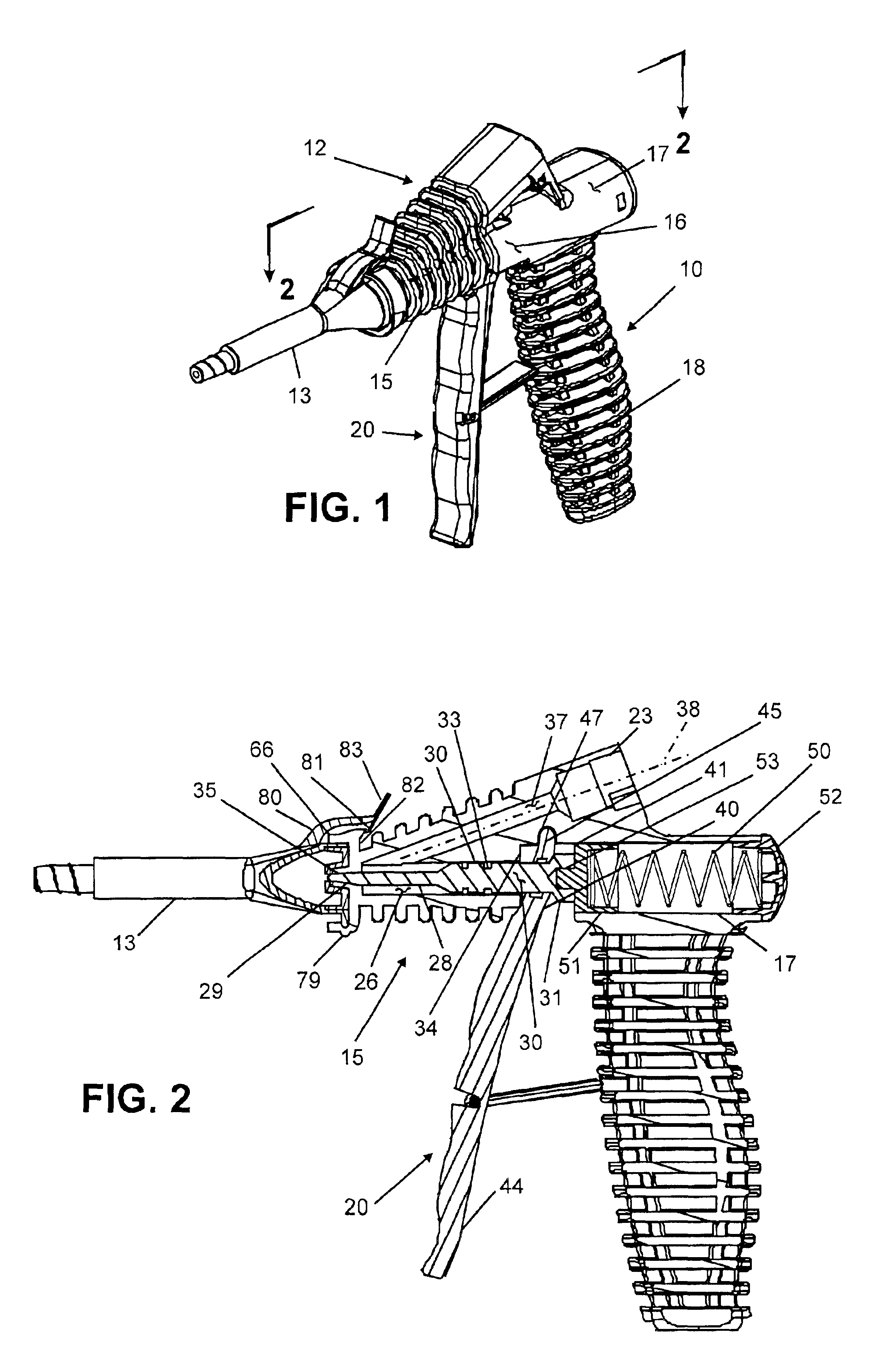
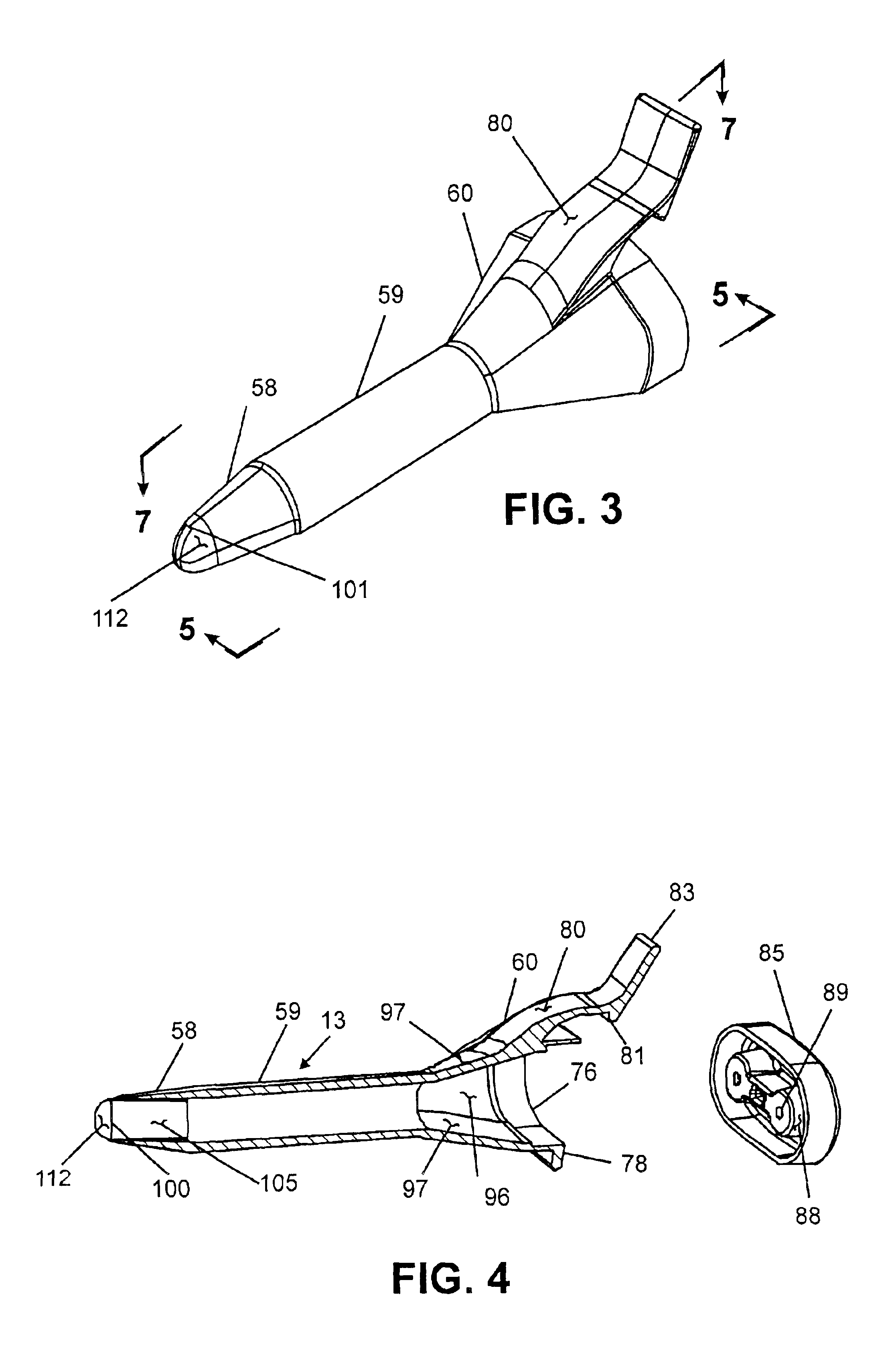
Referring now to the drawings wherein the showings are for the purpose of illustrating preferred and alternative embodiments of the invention and not necessarily limiting the invention, there is shown in perspective view in FIG. 1, an airless (as that term is defined in the Background) two-component dispensing gun 10. Dispensing gun 10 may be viewed as comprising a one-piece gun body 12 (which includes components to be described) to which is detachably secured a disposable nozzle 13. Reference can and should be had to parent U.S. application Ser. No. 09 / 471,994 (incorporated herein by reference) for a more detailed explanation of the of the operation and structure of gun 10 than that provided herein. In addition, FIGS. 1 and 2 are extracted from the parent application and show a nozzle having a conventional dispersing tip producing a cone shaped spray pattern. It is to be appreciated that in the preferred embodiment, dispersing gun 10 is sold as a part of a polyurethane foam dispens...


PUM

PropertyMeasurementUnit
acute angleaaaaaaaaaa
pressuresaaaaaaaaaa

Abstract

A disposable nozzle for an airless, polyurethane spray gun has an inlet chamber section sealingly latched to the gun nose for receiving polyurethane foam components, a mixing chamber section adjacent the inlet chamber containing a static mixer for mixing the polyurethane components and a dispensing tip section adjacent the mixing chamber for discharging the polyurethane as a spray. The dispensing tip has a longitudinally extending passage terminating at a rectangular opening in the tip defined by long side edges and short side edges. The length of the long side edges are generally maintained throughout the tip passage and approximate the diameter of the mixing chamber exit to produce a consistent rectangular fan spray pattern from the nozzle. Spray guide tabs extend from the long side edges of the rectangular tip opening to alleviate nozzle drip during dispensing.

Description

This invention relates generally to a dispensing apparatus for fluid products and more particularly to a nozzle for use with a hand held gun which mixes and dispenses two fluid components.The invention is particularly applicable and will be described with specific reference to a hand held dispensing gun for dispensing a two-component polyurethane foam. However, the invention in its broader application is not limited to polyurethane foams but has application to mixing and dispensing multi-component chemicals such as polyvinyls, paints, etc.BACKGROUNDThis invention is particularly suited for in situ applications of liquid chemicals mixed and dispensed as a spray or a foam and more specifically, to in situ application of polyurethane foam or froth. In situ applications for polyurethane foam have continued to increase in recent years extending the application of polyurethane foam beyond its traditional uses in the packaging, insulation and molding fields. For example, polyurethane foam ...

Claims


Application Information

Patent Timeline
Patent Type & Authority Patents(United States)
IPC IPC(8): B29B7/74B29B7/00B01F13/00B05B12/00
CPCB29B7/7438B05B12/002B01F13/002B01F2215/0039B05C17/00506B05C17/00516B05B12/0026B05B12/0024B05B1/3402B01F33/5011B01F2101/2305
Inventor HURRAY, PAUL GREGORYFISHBACK, THOMAS L.TAYLOR, ANTHONY J.
Owner ICP CONSTR INC
Learn More