Refiner force sensor

a technology of force sensor and refiner, which is applied in the direction of textiles and papermaking, grain treatment, papermaking, etc., can solve the problems of failure of standard pressure sensors, and insufficient parameters to fully characterize the refining action

Inactive Publication Date: 2005-01-11
QUEENS UNIV OF KINGSTON +3
View PDF6 Cites 7 Cited by
  • Summary
  • Abstract
  • Description
  • Claims
  • Application Information

AI Technical Summary

Problems solved by technology

However, it is widely known that this parameter is not sufficient to fully characterize the refining action, since vastly different pulp properties can be obtained at the same level of specific energy under different refining conditions.
The harsh conditions that exist within the refining zone of commercial refiners have proven too severe for standard pressure sensors.
These generally fail within a few minutes of operation in these conditions.
This choice of material is inadequate for long-term operation in an industrial refiner, since the sensor bar would wear much faster than the other refiner bars made of hardened material.

Method used


Image

  • Refiner force sensor
  • Refiner force sensor
  • Refiner force sensor

Examples


working example

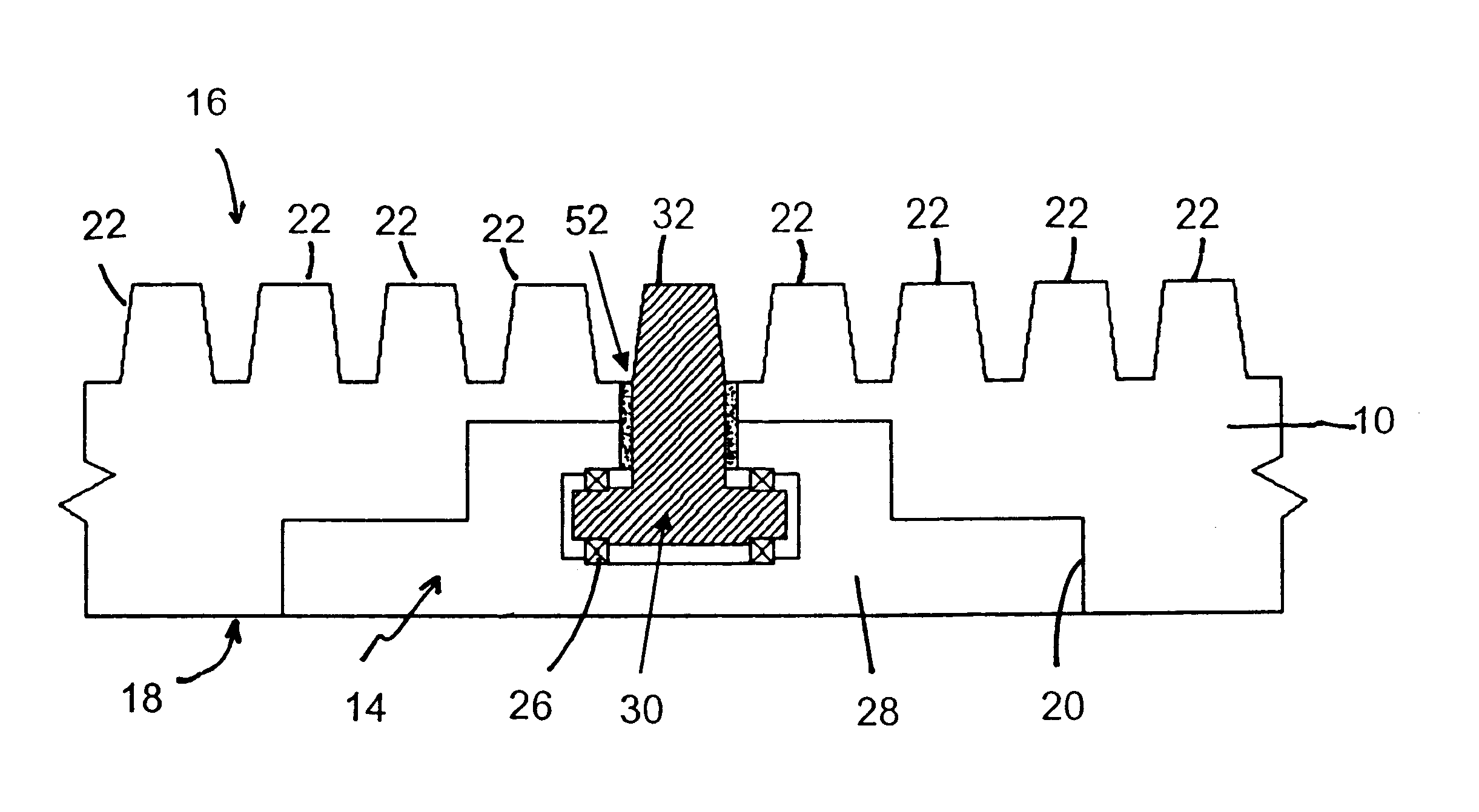
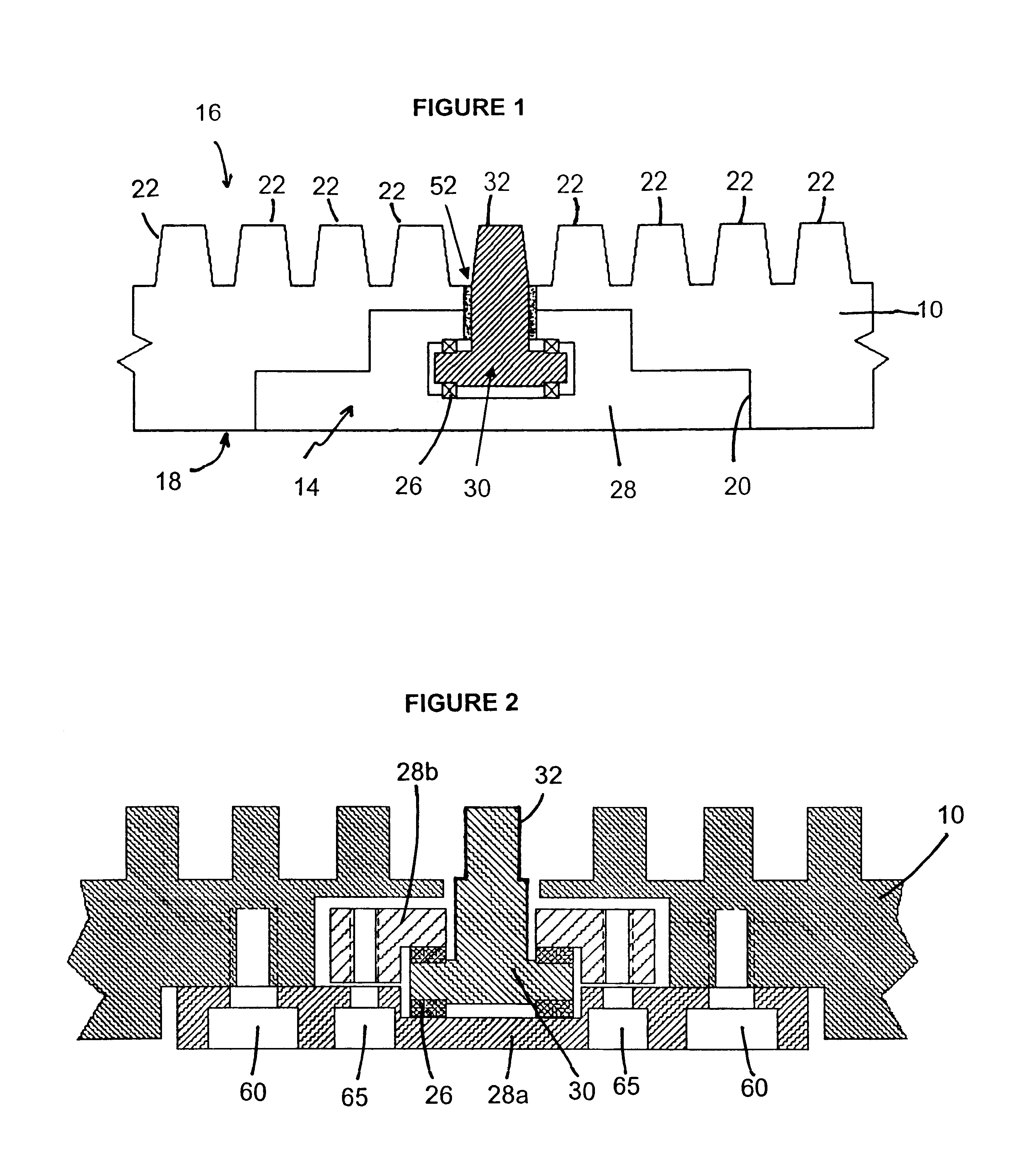
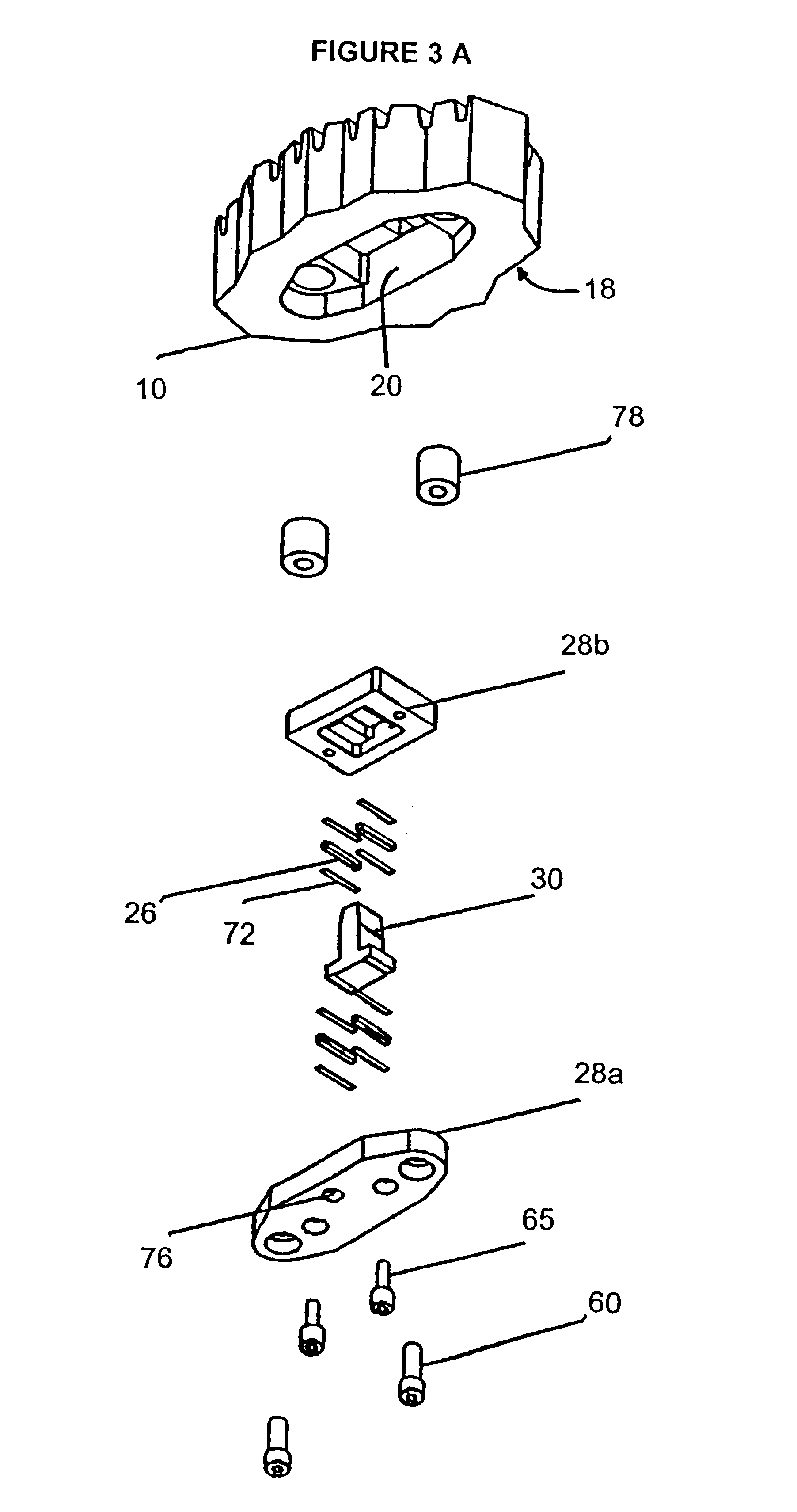
A force sensor according to the embodiment of FIG. 2 was installed in a laboratory refiner. The refiner had a diameter of 30 cm and operated at atmospheric pressure. The refiner was fed with chemi-thermomechanical pulp at a consistency of approximately 20%. FIGS. 17A and B show the normal and shear forces calculated using the signals from two of the piezo-ceramic element sensors 26. In FIG. 17A, the refiner was running at 1260 rpm, corresponding to a period of approximately 270 μs between bar passings (a bar-passing frequency of about 3.70 kHz). In FIG. 17B the refiner was running at a higher speed of 2594 rpm, corresponding to a bar-passing period of 131 μs (a bar-passing frequency of about 7.63 kHz). From these results, it can be seen that normal and shear forces related to individual bar crossings can be measured with a force sensor according to the present invention.

The piezo electric elements used in the initial testing above were found to have poor dimensional control. As a re...


PUM

PropertyMeasurementUnit
Curie temperatureaaaaaaaaaa
resonant frequencyaaaaaaaaaa

Abstract

This invention relates to a refiner force sensor for refiners used in the pulp and paper industry, to a refining apparatus, and to a method of measuring force acting on a refiner bar in a refiner.

Description

BACKGROUND OF THE INVENTIONi) Field of the InventionThe present invention relates to a refiner force sensor for refiners used in the pulp and paper industry, to a refining apparatus, and to a method of measuring forces acting on a refiner bar in a refiner.ii) Description of Prior ArtRefiners are used to produce pulp from wood chips or to modify the mechanical properties of wood fibres by repeatedly applying forces to the material processed by means of bars mounted on two opposing surfaces that move relative to one another.Refiners are commonly used in the pulp and paper industry to repeatedly subject wood fibres or wood chips to stresses and strains. In the case where wood chips are processed, the purpose is usually to separate wood fibres from one another to produce pulp that can later be used to manufacture paper or composite wood products such as hardboard. This process is generally conducted at high temperature and pressure in a steam environment, because a large amount of steam...

Claims


Application Information

Patent Timeline
Patent Type & Authority Patents(United States)
IPC IPC(8): D21D1/30D21D1/00
CPCD21D1/002D21D1/306D21D1/30
Inventor BANKES, ALAN HENRYWILD, PETER MARTINOUELLET, DANIELSHIARI, BEHROUZSIADAT, SEYED MOHAMMAD ALISENGER, JOHN JAA
Owner QUEENS UNIV OF KINGSTON
Why Eureka
Try Eureka