Lock with bendable shackle element openable in two ways
a shackle element and lock technology, applied in padlocks, building locks, constructions, etc., can solve the problems of bringing a user a lot of inconvenience or trouble, and being less convenient to opera
- Summary
- Abstract
- Description
- Claims
- Application Information
AI Technical Summary
Benefits of technology
Problems solved by technology
Method used
Image
Examples
first embodiment
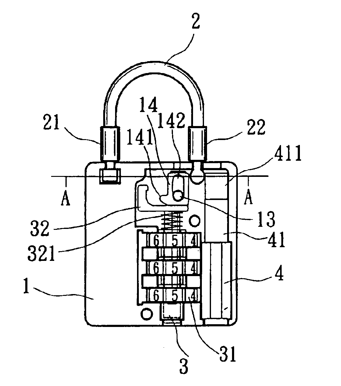
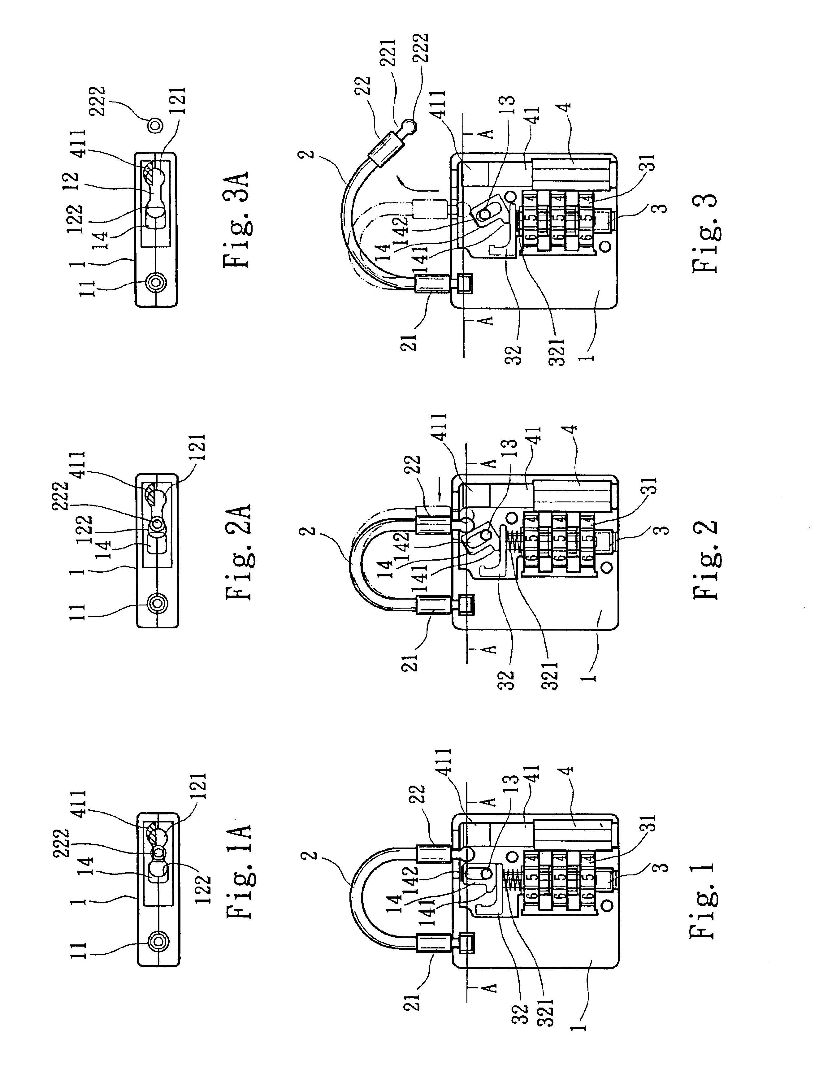
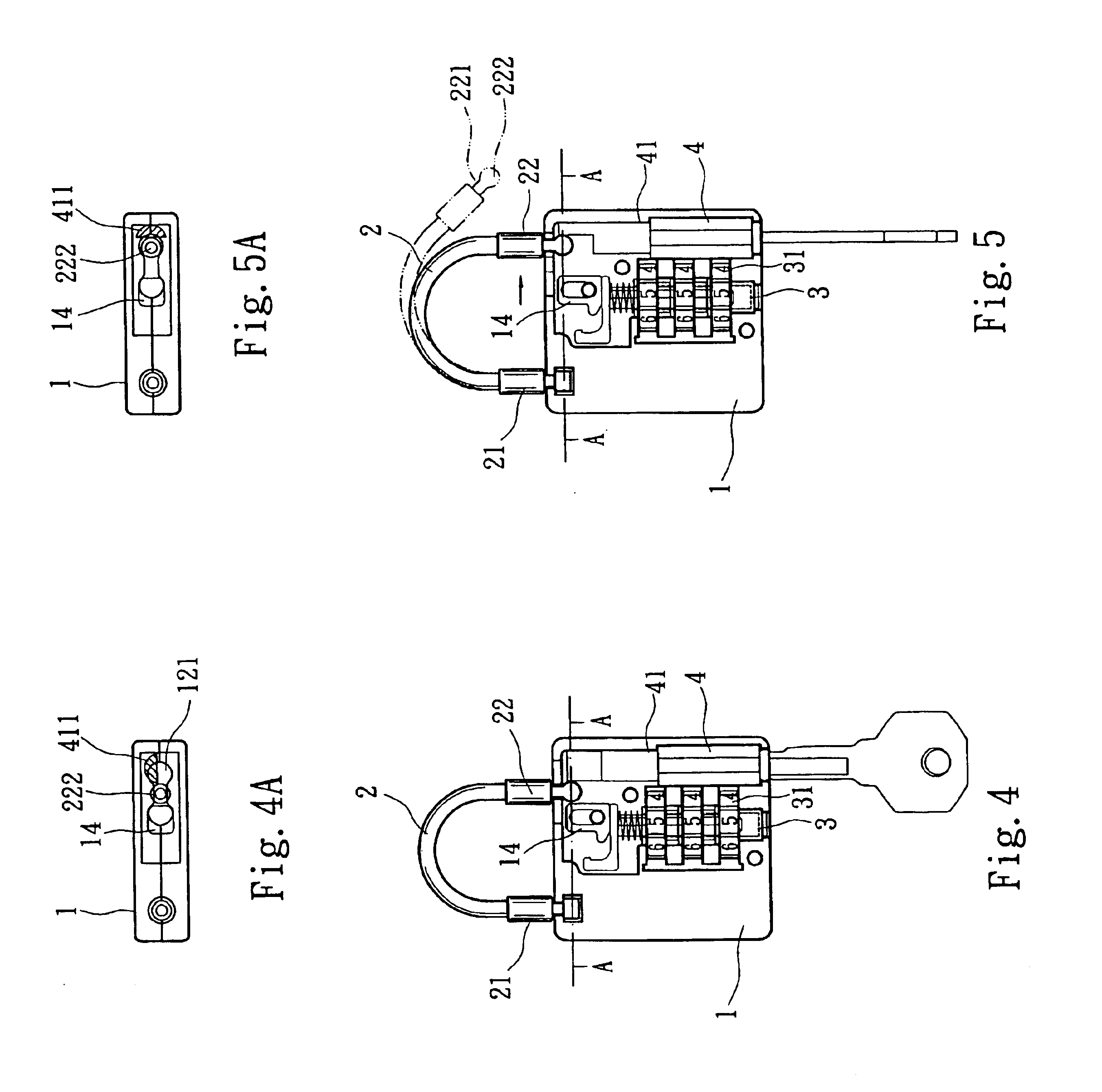
Please refer to FIG. 1 that is a schematical plan view of a lock according to the present invention, and to FIG. 1A that is a cross sectional view taken along line A—A of FIG. 1. As shown, the lock according to the present invention mainly includes a main body 1, a bendable shackle element 2, a combination lock core 3, and a key lock core 4. The main body 1 is provided at one peripheral wall thereof with a recess 11, and a locking slot 12 opposite to the recess 11. Two ends of the locking slot 12 are formed into a first locking hole 121 and a second locking hole 122 located between the first locking hole 121 and the recess 11. A horizontal shaft 13 is provided inside the main body 1 close to the second locking hole 122 to transversely extend through a long hole 142 on a shifting member 14. The shifting member 14 is provided at a lower side with a laterally projected nose portion 141.
The bendable shackle element 2 is a U-shaped flexible bar or tube, two ends of which are separately f...
second embodiment
FIG. 9 is a plan view showing an internal structure of the lock according to the present invention, wherein the lock is in a locked state. FIG. 10 shows the manner of unlocking the lock of FIG. 9 via the combination lock core 30. As shown in FIG. 9, when the lock is in a locked state, the spring 330 elastically pushes the combination lock core 30 for the pin portion 320 to engage with the annular groove 221 at the movable head 220 of the bendable shackle element 20. Meanwhile, the stop lug 420 at the free end of the turnable portion 410 of the key lock core 40 is locked at the other end of the long locking hole 120, such that the stopper 222 is firmly clamped between the pin portion 320 and the stop lug 420 without the risk of separating from the long locking hole 120. And, when the number rings 310 are turned to correct unlocking positions to release the combination lock core 30 from a locked state, the fixed head 210 of the bendable shackle element 20 may be pulled outward to sync...
PUM
 Abstract
Description
Claims
Application Information
 - R&D
- Intellectual Property
- Life Sciences
- Materials
- Tech Scout
- Unparalleled Data Quality
- Higher Quality Content
- 60% Fewer Hallucinations
Browse by: Latest US Patents, China's latest patents, Technical Efficacy Thesaurus, Application Domain, Technology Topic, Popular Technical Reports.
© 2025 PatSnap. All rights reserved.Legal|Privacy policy|Modern Slavery Act Transparency Statement|Sitemap|About US| Contact US: help@patsnap.com


