Pressure equalizing plunger valve for downhole use

a technology of pressure equalizer valve and plunger valve, which is applied in the direction of fluid removal, borehole/well accessories, construction, etc., can solve the problems of inability to maintain spare parts, inability to equalize the pressure in a cost-effective way, and inability to achieve the effect of reducing the resultant moment of the plunger

Inactive Publication Date: 2005-02-01
BAKER HUGHES INC
View PDF13 Cites 37 Cited by
  • Summary
  • Abstract
  • Description
  • Claims
  • Application Information

AI Technical Summary

Benefits of technology

An equalizer valve for a flapper in an SSV is disclosed. In one embodiment the plunger body is covered with a lubricious material in the bore in the flapper to counteract wear caused by off-center contact with the plunger by the flow tube. In another embodiment the flow tube and the plunger have matching angled surfaces to reduce the resultant moment of the plunger from offset contact of the flow tube. In another embodiment the flow tube contacts the plunger on center to eliminate a resultant moment, which can cause wear in the flapper bore or to the plunger.

Problems solved by technology

A pressure imbalance can occur because there is gas at low pressure above the flapper and high pressure from the formation below the flapper.
One costly way to equalize the pressure is to add heavy fluid above the flapper.
The problem was that each plunger 32 was custom fit to each bore 28 so that it was not possible to maintain a store of spare parts that could be counted on to provide adequate service.
Even with expensive machining, the problem of premature wear due to offset contact, created a reliability and maintenance concern.

Method used


Image

  • Pressure equalizing plunger valve for downhole use
  • Pressure equalizing plunger valve for downhole use
  • Pressure equalizing plunger valve for downhole use

Examples


Embodiment Construction

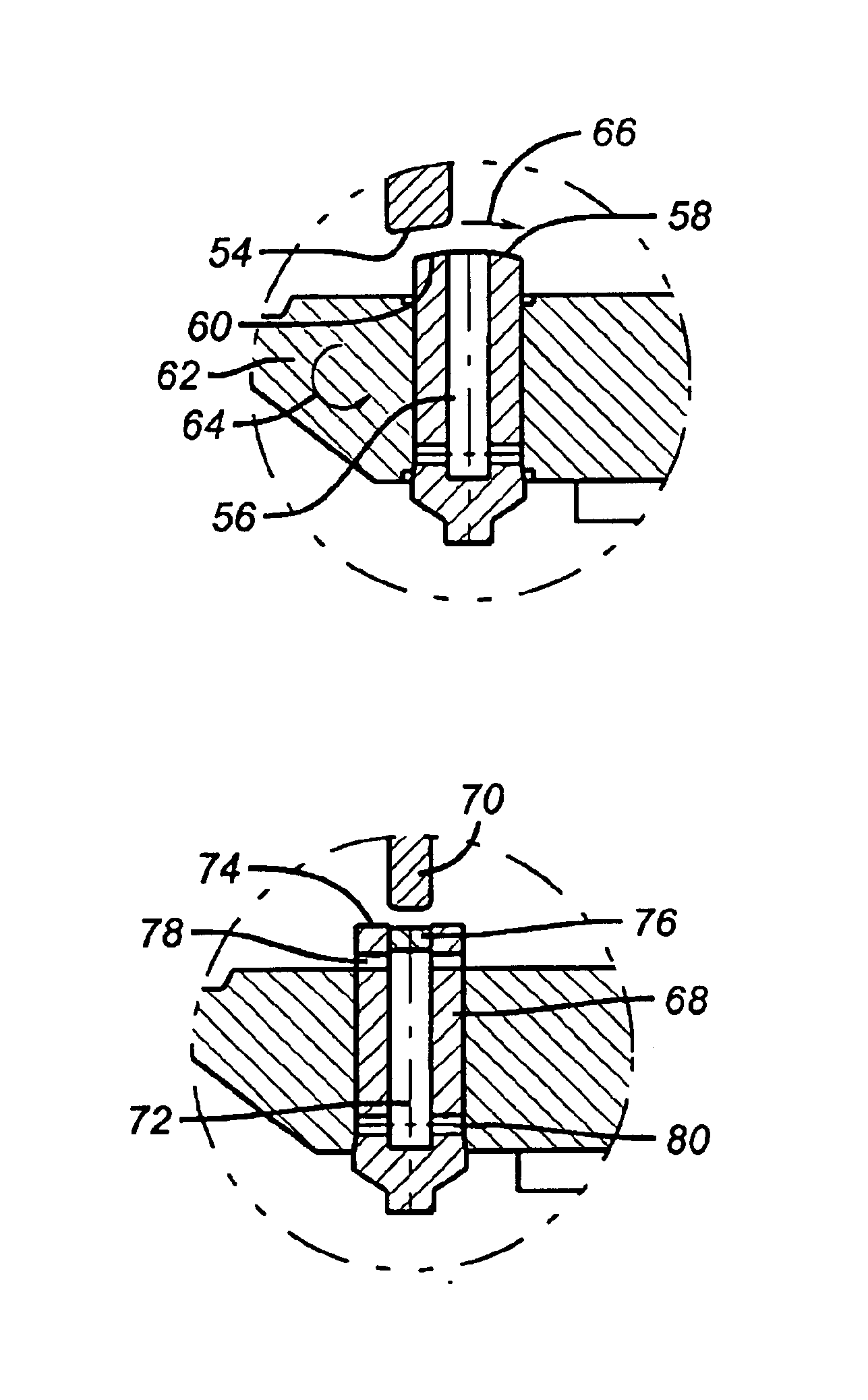
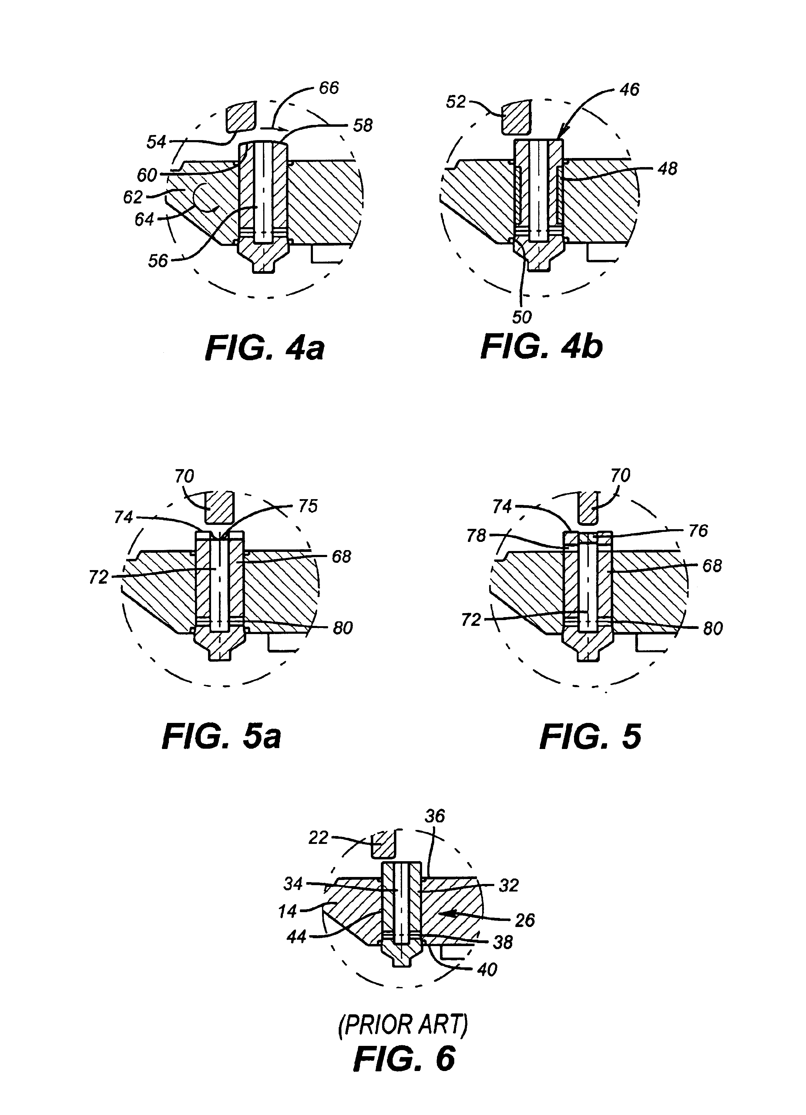
FIG. 4 illustrates two solutions to the problem of excessive wear on the plunger 46. A bearing 48, which can be in one or more pieces, can be mounted over the plunger 46 in bore 50. The bearing material is preferably PEEK or graphite filled Teflon. Using this solution, the flow tube 52 still hits the plunger 46 off center but the resultant moment does not result in wear of the plunger 46 or the bore 50. This is because the lubricious nature of the bearing 48. The clearance between the bearing 48, the plunger 46, and the bore 50 can be increased to greater than the about 0.001 inch clearance used with the prior technique where the bore 28 was machined after measuring the plunger 32. The polishing that was done in the past could also be minimized through the use of a bearing such as 48. Other materials could be used for the bearing 48, with those having lubricious qualities being preferred. Clearly the choice of materials must take into account the surrounding well conditions such as ...


PUM


Abstract

An equalizer valve for a flapper in an SSV has one embodiment where the plunger body is covered with a lubricious material in the bore in the flapper to counteract wear caused by off-center contact with the plunger by the flow tube. In another embodiment the flow tube and the plunger have matching angled surfaces to reduce the resultant moment of the plunger from offset contact of the flow tube. In another embodiment the flow tube contacts the plunger on center to eliminate a resultant moment, which can cause wear in the flapper bore or to the plunger.

Description

FIELD OF THE INVENTIONThe field of the invention is downhole valves and, more particularly, plunger type equalizer valves mounted to flappers in downhole safety valves.BACKGROUND OF THE INVENTIONWells typically contain sub-surface safety valves (SSV), which are actuated from the surface through a control line, which runs down to the valve. These valves have a biased closure member, known as a flapper. The flapper is biased into contact with a mating seat for isolation of a zone in the well from the surface. The flapper is positioned perpendicularly to the longitudinal axis of the wellbore, when it is in the closed position. To open the valve, pressure through the control line causes a flow tube to shift against a bias force. The flow tube engages the flapper to rotate it 90 degrees. The flow tube continues to advance as the flapper is positioned behind it.In certain wells, with the SSV closed and formation pressure acting on the flapper in the closed position, it is desirable to equ...

Claims


Application Information

Patent Timeline
Patent Type & Authority Patents(United States)
IPC IPC(8): E21B34/00E21B34/10
CPCE21B34/101E21B2034/005E21B2200/05
Inventor MYERLEY, THOMAS S.
Owner BAKER HUGHES INC
Why Eureka
Try Eureka