Dynamic histogram equalization for high dynamic range images

a dynamic range and image technology, applied in image enhancement, instruments, television systems, etc., can solve the problems of affecting the image quality of the image, the brightest part of the image or the darkest part of the image is often lost, and the device typically only displays 8-bit images, etc., to achieve the effect of rapid change of image characteristics

Inactive Publication Date: 2005-02-01
APTINA IMAGING CORP
View PDF8 Cites 91 Cited by
  • Summary
  • Abstract
  • Description
  • Claims
  • Application Information

AI Technical Summary

Benefits of technology

According to the present system, this is done by using a local tr

Problems solved by technology

However, conventional display devices typically only display 8-bit-images.
If the same quantization step is used in an attemp

Method used


Image

  • Dynamic histogram equalization for high dynamic range images
  • Dynamic histogram equalization for high dynamic range images
  • Dynamic histogram equalization for high dynamic range images

Examples


Embodiment Construction

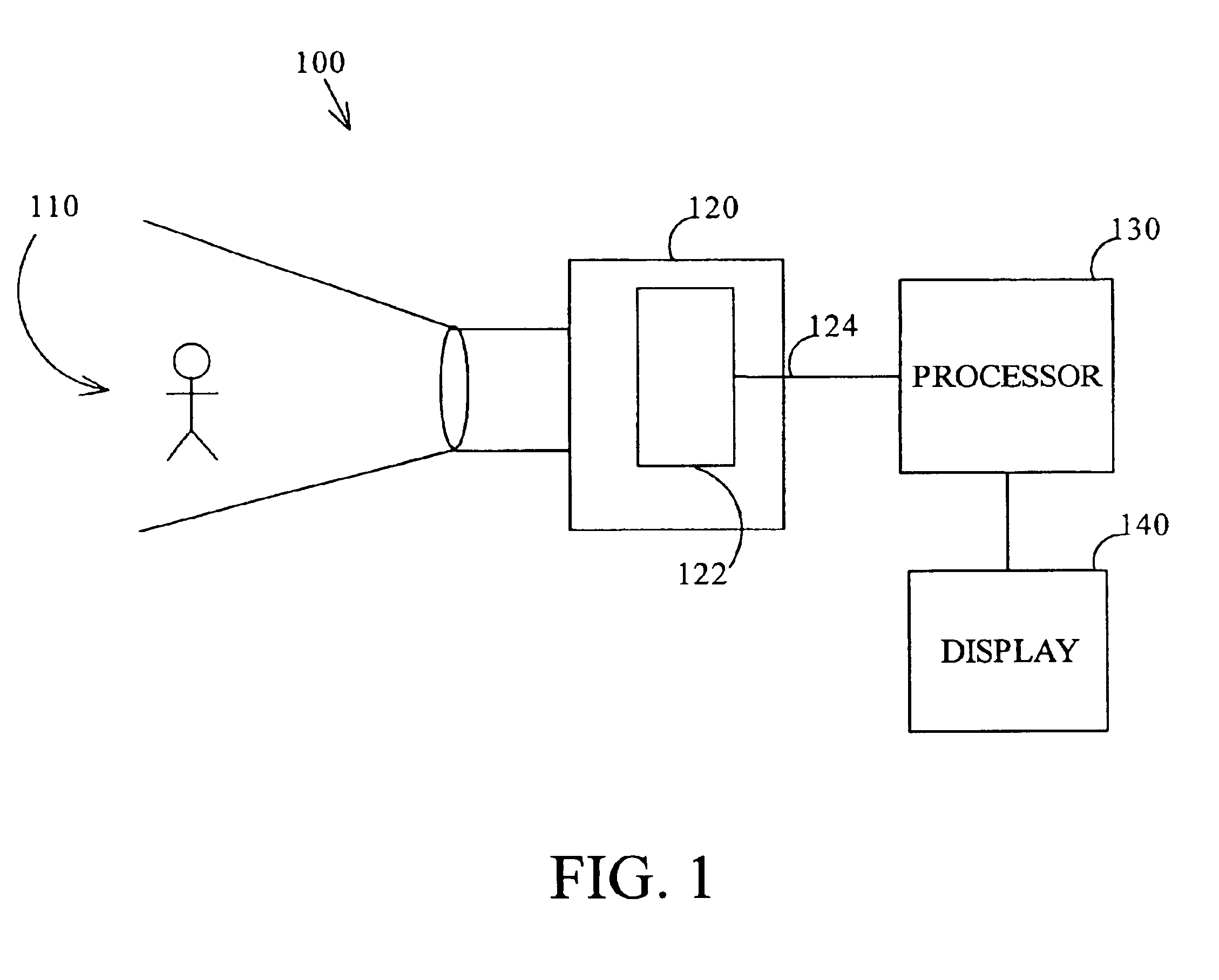
An embodiment is shown in FIG. 1. In the FIG. 1 embodiment, an imaging system, generally shown as 100, obtains an image of the scene 110. The image may be obtained by an image acquisition device 120, which may include an active pixel sensor 122 receiving light indicative of the image of the scene 110, and converting that light into a signal 124 indicative of pixel-level received signals. A processor 130 may process this image in a specified way as described herein, to reduce the number of bits of signal dynamic range. The output of the processor may be displayed on the display 140. For this purpose, the processor 130 may also include a display driver.

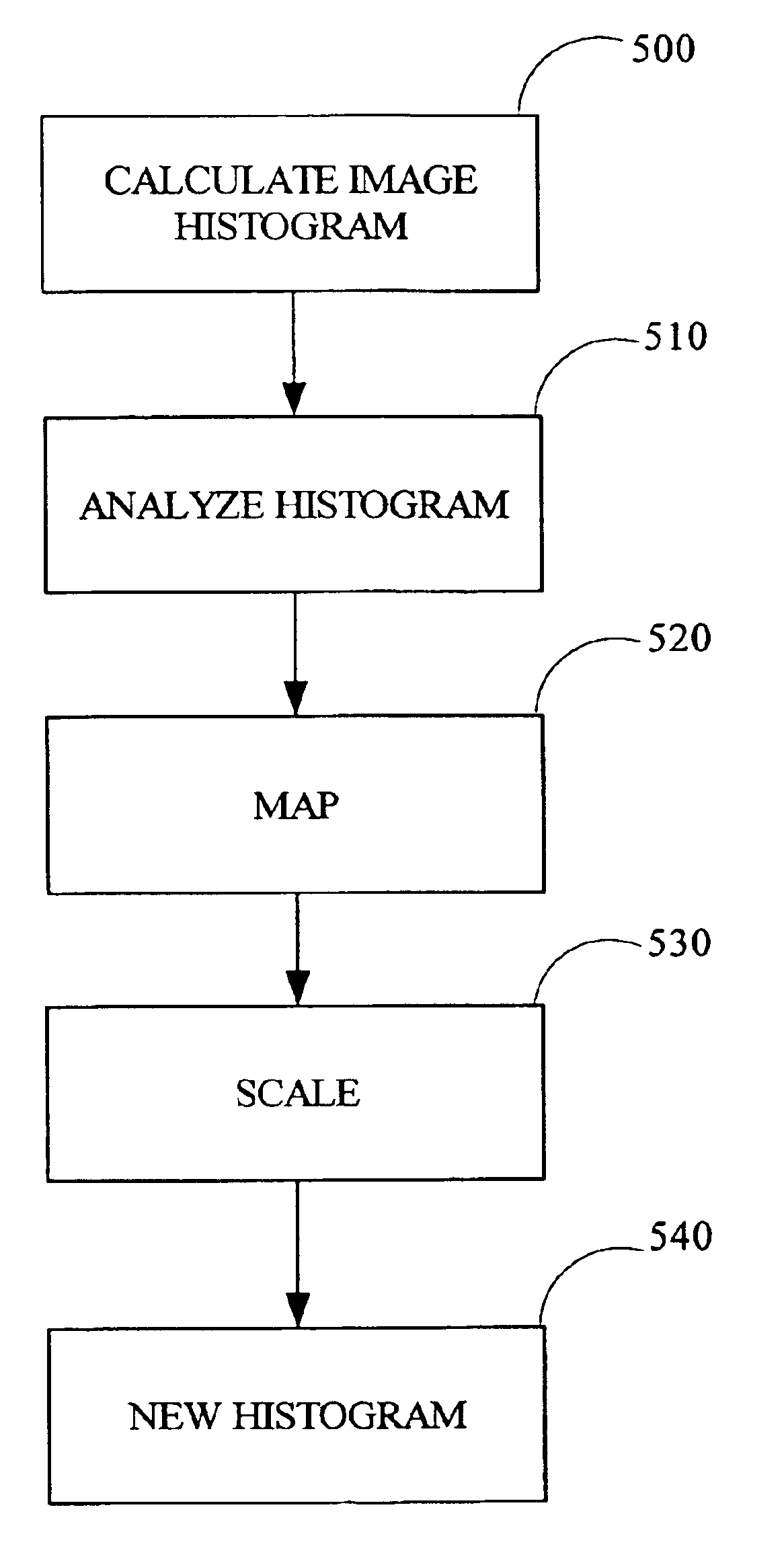
In this embodiment, the image 124, which is produced by the image sensor 122, may have a higher dynamic range that is capable of being displayed on display 140. Accordingly, the operation of the present system modifies the histogram of the mage. The processor does this by carrying out the flowchart of FIG. 5.

At 500, an initial operation...


PUM


Abstract

Dynamic range equalization by histogram modification. A histogram is analyzed to determine locations of peaks. A mapping function is formed which relates to the locations of the peaks in a histogram. That mapping function may have areas of highest slope near the peaks. The mapping function is used to form a compressed histogram, which has the required number of levels to display on a display device.

Description

BACKGROUNDImages can be represented as electronic versions of the scene being viewed. The electronic image may represent a scene to that has a very high dynamic range, e.g. 18 bits or more of dynamic range. However, conventional display devices typically only display 8-bit-images. Therefore, it is often necessary to display a higher dynamic range scene on a lower dynamic range viewing device.If the same quantization step is used in an attempt to make this display operation, then either the brightest part of the image or the darkest part of the image is often lost.SUMMARYThe present application teaches nonlinearly mapping an image with higher number of bits to an image with a smaller number of bits, while preserving at least part of the local contrast.According to the present system, this is done by using a local transformation that can rapidly change characteristics of the image.BRIEF DESCRIPTION OF THE DRAWINGSThese and other aspects will now be described in detail with reference t...

Claims


Application Information

Patent Timeline
IPC IPC(8): G06K9/00G06T5/40
CPCG06T5/009H04N5/20G06T5/40G06T2207/20208
Inventor WANG, YIBING MICHELLE
Owner APTINA IMAGING CORP
Why Eureka
Try Eureka