Circuit breaker trip unit including a plunger resetting a trip actuator mechanism and a trip bar

a circuit breaker and trip unit technology, applied in the direction of protective switch, electrical apparatus, protective switch operating/releasing mechanism, etc., can solve the problems of magnetic field, inconsistency of the magnets and malfunction of the tripping devi

Inactive Publication Date: 2005-02-08
EATON INTELLIGENT POWER LTD
View PDF9 Cites 37 Cited by
  • Summary
  • Abstract
  • Description
  • Claims
  • Application Information

AI Technical Summary

Problems solved by technology

One of the most frequent problems with molded case electronic trip units is the malfunctioning of the tripping device.
The main problem with the existing trip actuators is the inconsistency of their magnets and therefore, the magnetic field.
Also, since the existing technology uses pre-magnetized magnets, the assembly process is difficult.

Method used


Image

  • Circuit breaker trip unit including a plunger resetting a trip actuator mechanism and a trip bar
  • Circuit breaker trip unit including a plunger resetting a trip actuator mechanism and a trip bar
  • Circuit breaker trip unit including a plunger resetting a trip actuator mechanism and a trip bar

Examples


Embodiment Construction

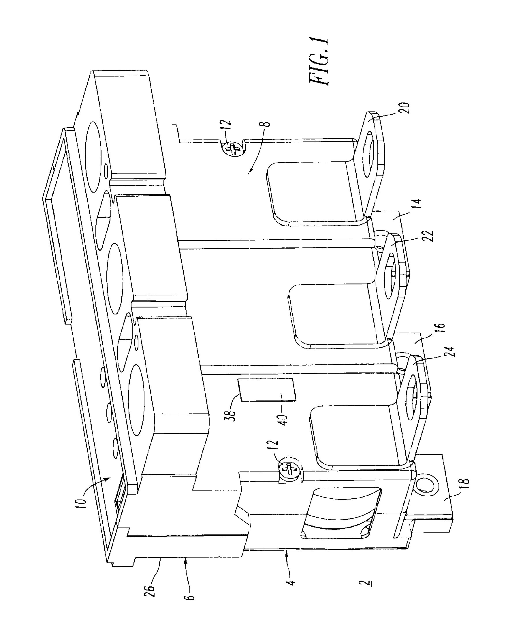
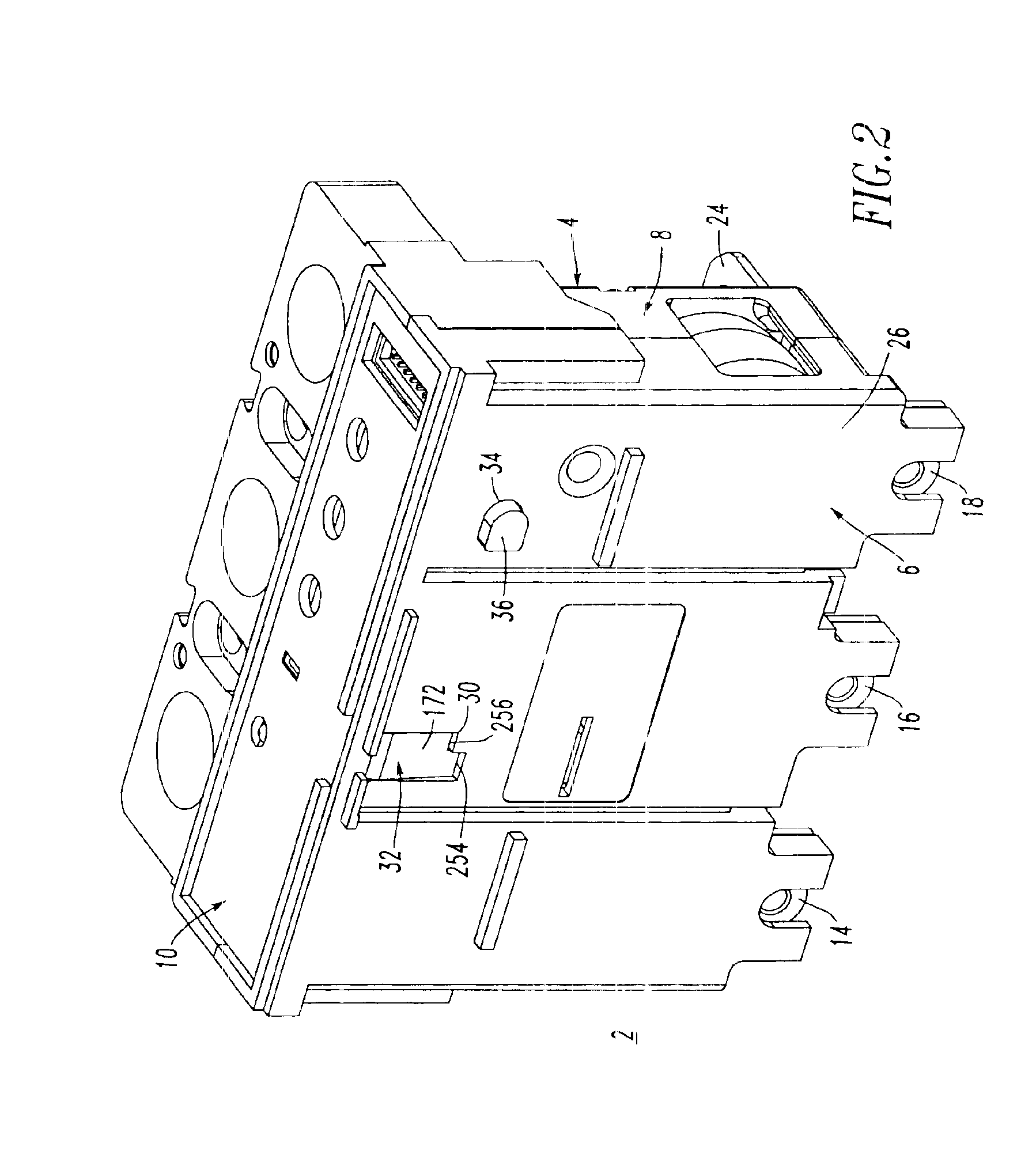
Referring to FIGS. 1 and 2, a trip unit 2 is shown. The trip unit 2 includes a molded housing 4 having a base 6, a cover 8 and a top portion 10. A pair of screws 12 secures the cover 8 to the base 6. Disposed from the base 6 are three-phase line end terminals 14, 16, 18. The cover 8 includes corresponding load end terminals 20, 22, 24, respectively.

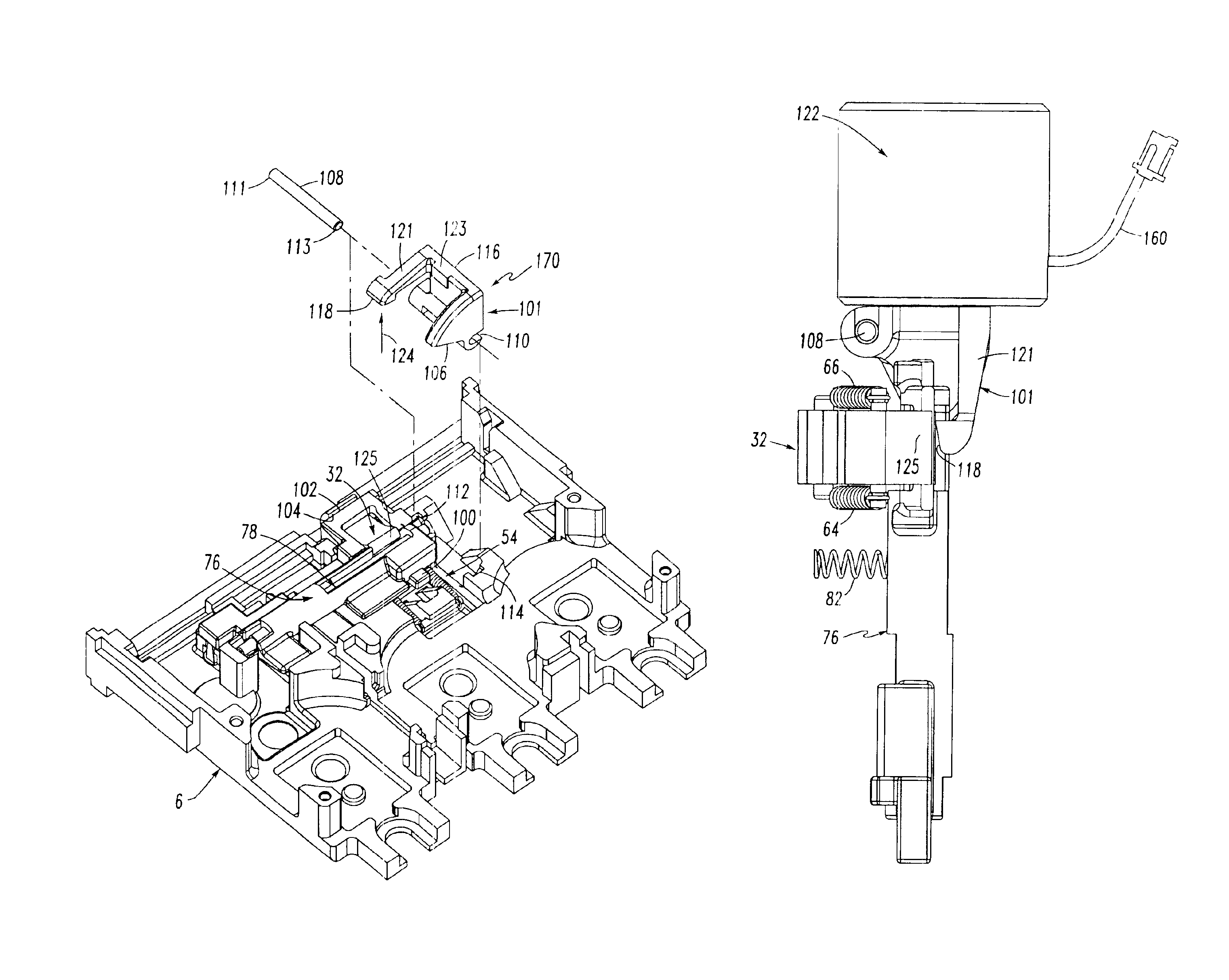
The base 6 includes a surface 26 (as shown in FIG. 2), which is disposed adjacent to a circuit breaker frame 28 as shown in FIG. 21. The trip unit 2 is advantageously adapted for engagement within and disengagement from the circuit breaker frame 28. The base surface 26 includes an opening 30 for a plunger, such as a rotary plunger 32 (as best shown in FIG. 15), and an opening 34 for an attachment button 36 (as best shown in FIG. 3). As discussed below in connection with FIGS. 4 and 18-20, the rotary plunger 32 is pivotally mounted with respect to the housing 4 and includes a first or on position (FIG. 18), a second or tripped position (FI...


PUM


Abstract

A trip unit includes a housing, a rotary plunger mounted in the housing and a pivotal trip bar also mounted therein. The trip bar latches the plunger in an on position, releases the plunger to a tripped position and re-latches the plunger. A set of springs biases the plunger to the tripped position. A rotary trip lever is pivotally mounted in the housing. A trip solenoid includes a linear plunger, which resets the solenoid when retracted, and which engages and rotates the trip lever when extended, in order to rotate the trip bar and release the rotary plunger. The rotary plunger engages the rotary trip lever when reset and rotates the same in an opposite direction, in order to retract the linear plunger and reset the solenoid. During that reset operation, the rotary plunger also cams the trip bar, in order to re-latch the rotary plunger in the on position.

Description

BACKGROUND OF THE INVENTION1. Field of the InventionThis invention relates to electrical switching apparatus and, more particularly, to circuit breaker trip units.2. Background InformationCircuit breakers and circuit breaker trip units are well known in the art. See, for example, U.S. Pat. Nos. 5,910,760; and 6,144,271.Resetting of a circuit breaker (e.g., through the operating handle and operating mechanism thereof) is accomplished in a manner well known in the art and is described and shown, for example, in U.S. Pat. No. 5,910,760.As disclosed in U.S. Pat. No. 6,144,271, a linear plunger of the trip unit is employed to trip open the associated circuit breaker frame whenever the linear plunger is extended from the trip unit. Actuation of primary and secondary frame latches occurs exclusively by way of the extended and resetable trip unit linear plunger, which is, otherwise, normally contained entirely within the trip unit. The secondary frame latch is in disposition to be struck by...

Claims


Application Information

Patent Timeline
Patent Type & Authority Patents(United States)
IPC IPC(8): H01H71/12H01H71/00H01H71/74
CPCH01H71/12H01H71/123H01H2071/508H01H71/7409
Inventor PUSKAR, MICHAEL P.WHITAKER, THOMAS A.RANDAL, WILLIAM M.CARLINO, HARRY J.
Owner EATON INTELLIGENT POWER LTD
Why Eureka
Try Eureka