Electrolytic capacitor and a fuel cell drive car using the capacitor

a technology of electrolytic capacitor and fuel cell, which is applied in the direction of electrolytic capacitor, liquid electrolytic capacitor, electrolytic generator, etc., can solve the problems of shortening the life of the capacitor, requiring a long time for charging and discharging, and few conventional electrolytic capacitors instantaneously discharge charges

Inactive Publication Date: 2005-02-08
JELMAX
View PDF4 Cites 11 Cited by
  • Summary
  • Abstract
  • Description
  • Claims
  • Application Information

AI Technical Summary

Benefits of technology

In the electrolytic capacitor according to the invention, the first and second separator paper of the ion permeable compound separator are papers made of natural fiber, and the fiber density of the first separator paper contacting with the dielectric film which is provided on the surface of the anode foil is higher than the fiber density of the second separator paper.

Problems solved by technology

However, few of the conventional electrolytic capacitors instanteneously discharge the charges stored, because they have an ion conduction structure.
That is, generally, conventional electrolytic capacitors need a long time for charging and discharging.
As a result, heat and a lot of hydrogen gas are generated from a surface of the cathode, which shortens the life of the capacitor remarkably.

Method used


Image

  • Electrolytic capacitor and a fuel cell drive car using the capacitor
  • Electrolytic capacitor and a fuel cell drive car using the capacitor
  • Electrolytic capacitor and a fuel cell drive car using the capacitor

Examples


Embodiment Construction

The embodiment of the invention will be explained in detail referring to the accompanying figures.

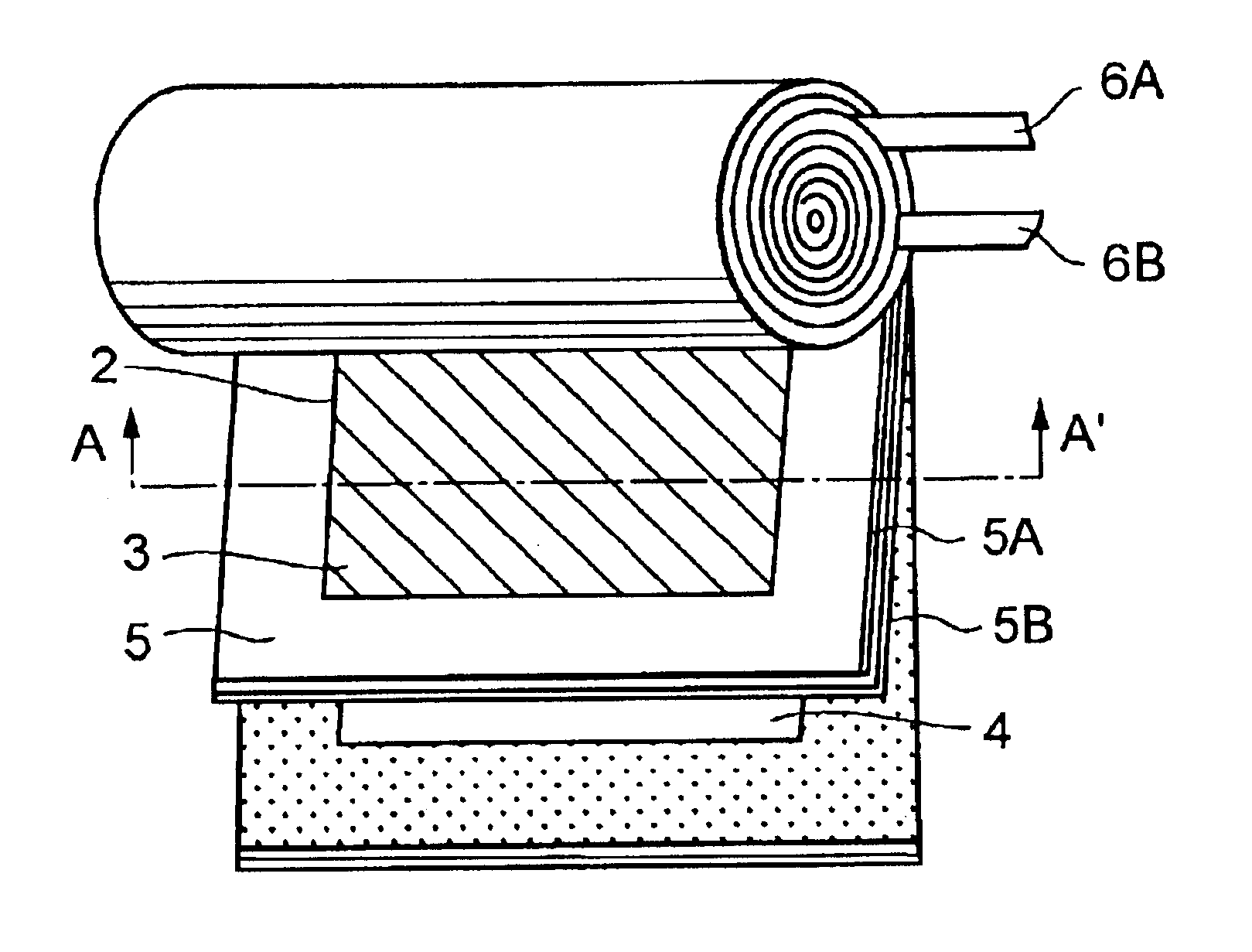
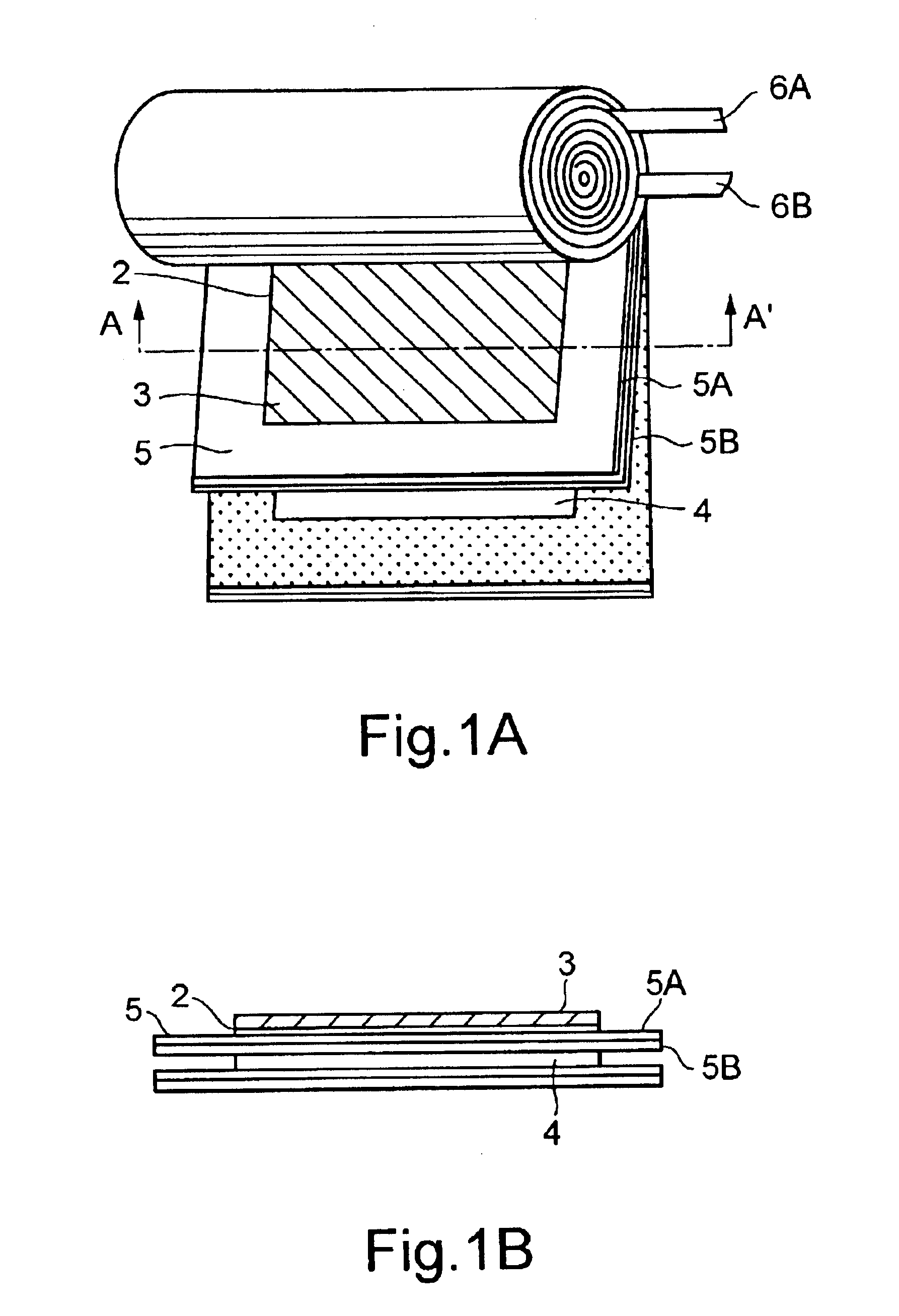
FIG. 1A and FIG. 1B are views showing an electrolytic capacitor according to the present invention, wherein FIG. 1A is a developed perspective view, and FIG. 1B is the sectional view along the A-A′ line in the figure FIG. 1A.

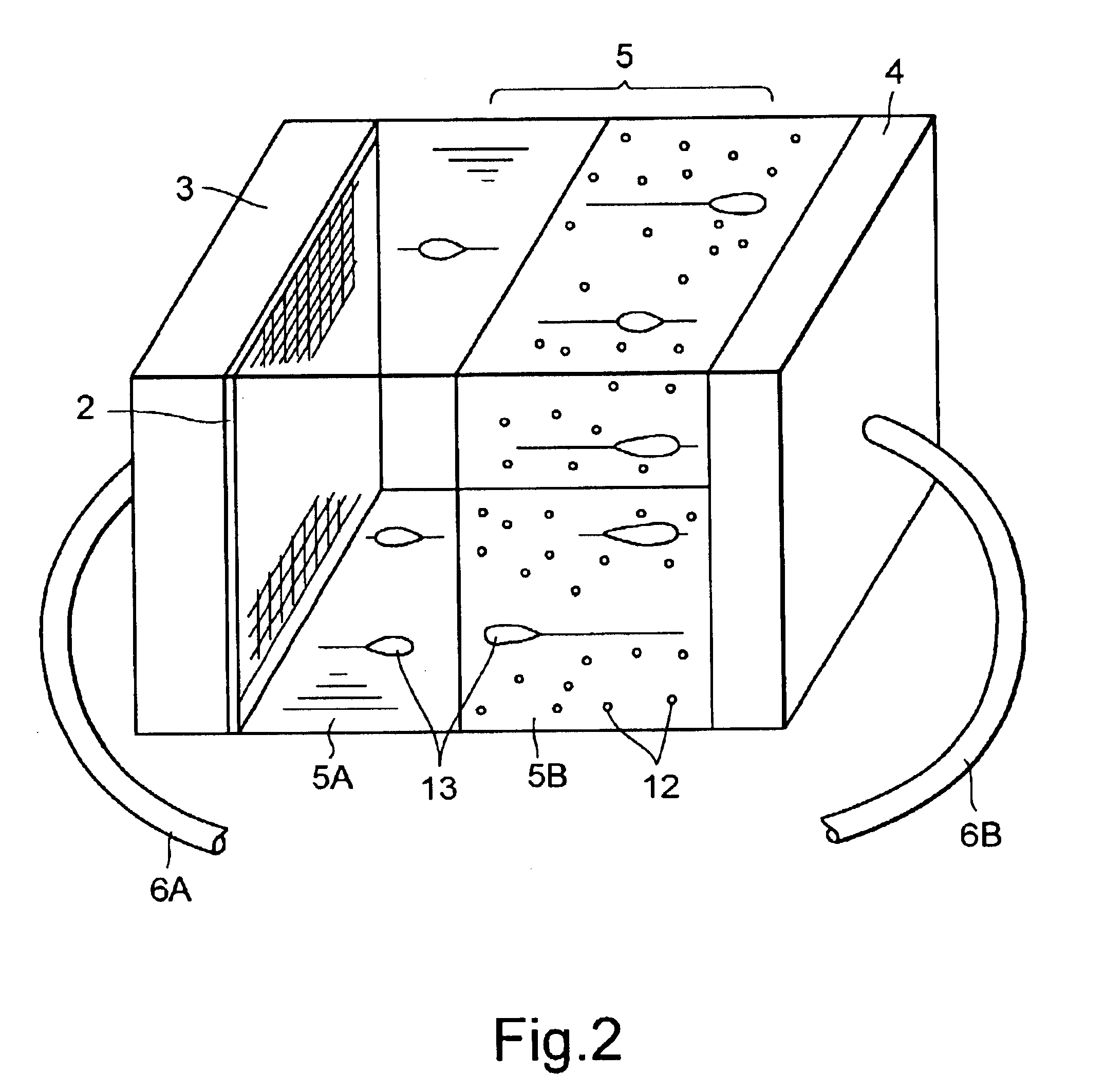
As shown in FIG. 1A, an anode foil 3 and a cathode foil 4 are arranged to face each other. On the lower side of foils 3, a dielectric film 2 is provided. The anode foil 3 and the cathode foil 4 are made of, for example, aluminum, and the dielectric film 2 is an oxide film formed by oxidizing the surface of the anode aluminum foil.

An ion permeable compound separator 5 is arranged between the anode foil 3 and cathode foil 4. The ion permeability compound separator 5 consists of a first separator paper 5A and a second and separator paper 5B, which are ion permeable capacitor papers such as Manila papers and the like comprising natural fibers as a main component and are...


PUM


Abstract

Electrolytic capacitor for of a high voltage and a high capacity is provided, which is suited for an auxiliary power supply of a fuel cell vehicle. A cathode and an anode foil are arranged to face each other. A dielectric film may be provided on the surface of the anode foil. The anode foil and the cathode foil 4 are wound into a roll, with a compound separator including the first and second separators and arranged there between. In the compound separator, electrolyte is impregnated and conductive fine particles are dispersed in the second separator.

Description

CROSS-REFERENCE TO RELATED APPLICATIONSThis application is based upon and claims the benefit of priority from the prior Japanese Patent Application No. 2003-078404 filed on Mar. 20, 2003; the entire contents of which are incorporated herein by reference.BACKGROUND OF THE INVENTIONThe present invention relates to an electrolytic capacitor which can be rapidly charged and discharged with electric charge of high voltage and large capacity, and more particularly to an electrolytic capacitor used as an auxiliary power source for cars or other vehicles which use fuel cells as a power source.In recent years, development of fuel cell vehicles (FC vehicles) is very rapid. A fuel cell for the FC vehicles is supplied with high-pressure hydrogen as fuel and is used as a power source replacing a gasoline engine. This FC vehicle uses the DC electric power which is generated by the fuel cell, and drives DC motors directly. Thus, it attracts attention all over the world as a most efficient power so...

Claims


Application Information

Patent Timeline
Patent Type & Authority Patents(United States)
IPC IPC(8): H01G9/00H01G9/02
CPCH01G9/00
Inventor ISHII, KAZUO
Owner JELMAX
Why Eureka
Try Eureka