
Method of producing a composite structure via intermediate products, the related apparatus and a composite structure obtainable by the method

a composite structure and intermediate product technology, applied in the field of producing a composite structure, can solve the problems of increasing length, increasing the height of the ceiling in the hall where the blades are manufactured, and increasing the size of the moulding assembly for such blades

Active Publication Date: 2015-12-29
LM GLASSFIBER
View PDF12 Cites 5 Cited by
  • Summary
  • Abstract
  • Description
  • Claims
  • Application Information

AI Technical Summary

Benefits of technology

This patent describes a method of producing composite structures by manufacturing separate smaller structures and then molding them together using liquid resin. This method has advantages over traditional methods of connecting composite structures, as it does not have any boundary surfaces that could weaken the structure. The method also allows for a stronger connection, as the fiber layers have a higher density in the connection. Additionally, the ends of the composite structures can be designed to maximize strength and minimize the occurrence of weak spots. The method also results in an intermediate composite part that is stronger than other parts of the structure.

Problems solved by technology

Wind turbine blades have become increasingly longer over the years and blades of more than 60 meters are mass-produced, which means that mould assemblies for moulding such blades also have become increasingly larger.
This results in problems in regard to the mould assemblies used, since the mould part rotating with respect to the other one during closure of the mould assembly reaches a very great height during the rotary motion, which may entail that the height of the ceiling in the halls where the blades are manufactured must be very great.
This means that the halls become more expensive to build, or that the ceilings in existing halls have to be raised, which of course also results in higher financial costs.
Furthermore, transport of these large composite structures is problematic.
However, prior art blades divided into separate sections are joined via mechanical connection means, which introduces a mechanical interface which during use of the wind turbine blade can lead to local weaknesses and at worst cause a breakdown.

Method used


Image

  • Method of producing a composite structure via intermediate products, the related apparatus and a composite structure obtainable by the method
  • Method of producing a composite structure via intermediate products, the related apparatus and a composite structure obtainable by the method
  • Method of producing a composite structure via intermediate products, the related apparatus and a composite structure obtainable by the method

Examples


Embodiment Construction

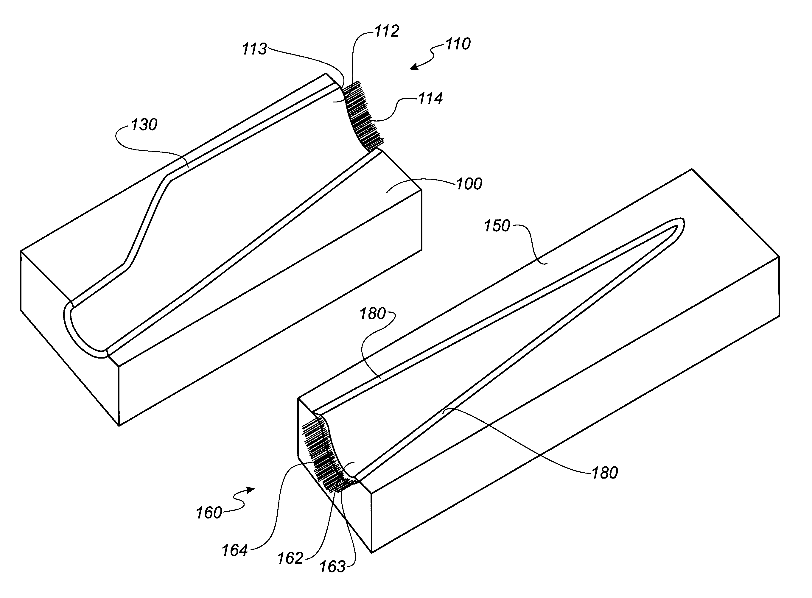
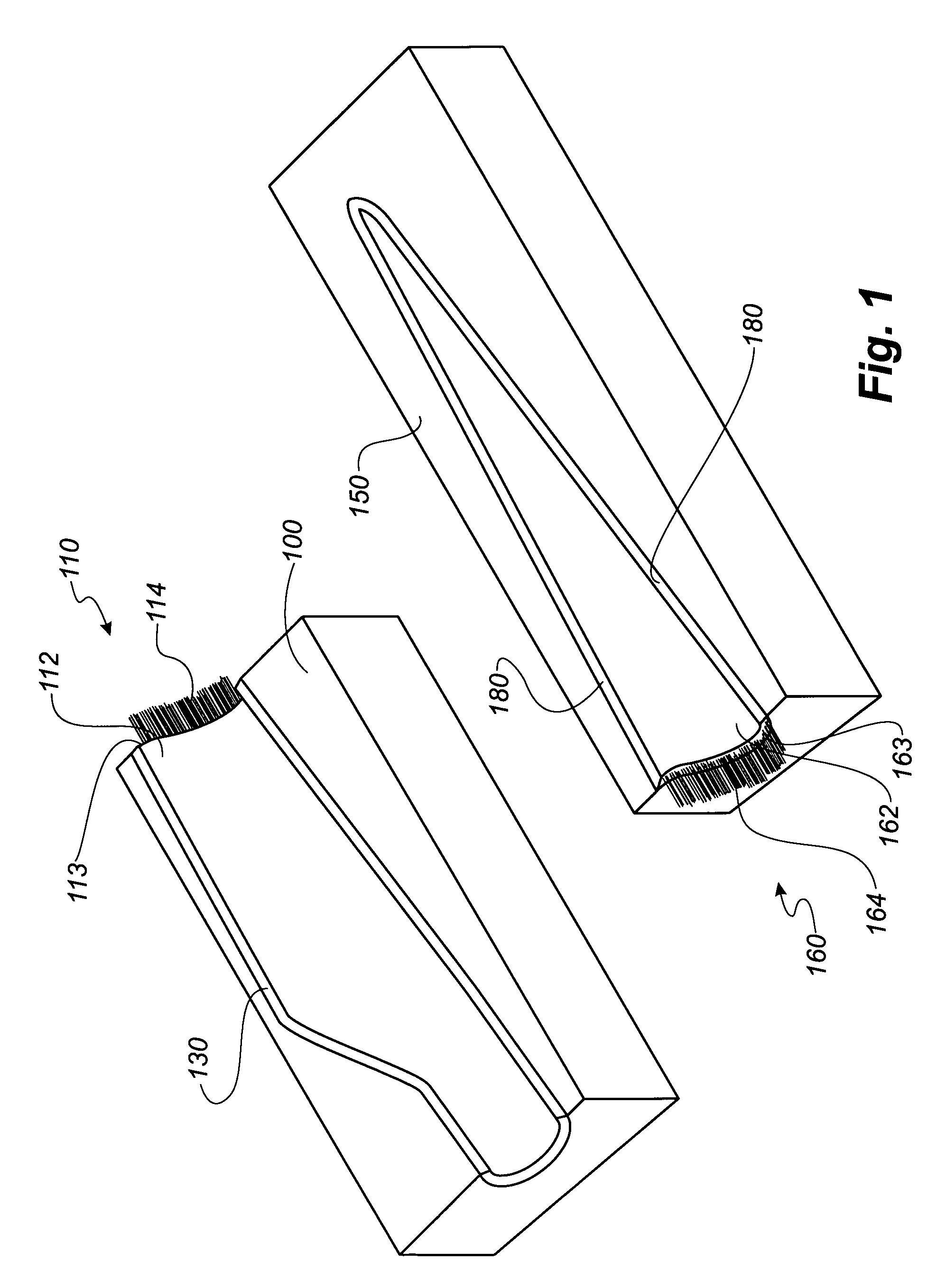
[0051]FIG. 1 shows a first mould part 100 with a first moulded structure in form of a first blade shell part 110 according to the invention, and a second mould part 150 with a second moulded structure in form of a second blade shell part 160 according to the invention. The blade shell parts 150, 160 are sectional shell parts of a pressure side of a wind turbine blade, where the first blade shell part 150 forms a part of the blade, which is closest to a hub and includes the root area when the blade is mounted to the hub of a wind turbine blade, and the second blade shell part 160 forms a part of the blade, which is furthest from the hub and includes the blade tip.

[0052]The first blade shell part 110 includes a first cured composite part 112, which has been moulded in a moulding surface of the first mould part 100. The first cured composite part 112 comprises a fibre-reinforced polymer material and can be manufactured by any conventional methods, such as the VARTM method. The first cu...


PUM

PropertyMeasurementUnit
thicknessaaaaaaaaaa
pressureaaaaaaaaaa
vacuumaaaaaaaaaa

Abstract

A method of producing a composite structure comprising fiber reinforced material and having a longitudinal direction is described. The method comprises the following steps: a) manufacturing a first structure comprising a first cured composite part having a first thickness and a longitudinal direction with a first end, and a number of first fiber layers extending from the first end, b) manufacturing a second structure comprising a second cured composite part having a second thickness and a longitudinal direction with a second end, and a number of second fiber layers extending from the second end, and c) arranging the first structure and the second structure so that the first end faces towards the second end, and arranging the first fiber layers and the second fiber layers so that at least a part of the first fiber layers overlap at least a part of the second fiber layers in the longitudinal direction, d) supplying liquid resin in order to impregnate the first fiber layers and the second fiber layers, and e) curing the liquid resin in order to form the composite structure comprising the first cured composite part, the second cured composite part, and an intermediate composite part including the first fiber layers and the second fiber layers.

Description

[0001]This is a National Phase Application filed under 35 USC 371 of International Application No. PCT / DK2008 / 000297, filed on Aug. 22, 2008, an application claiming foreign priority benefits under 35 USC 119 of European Application No. 07388067.6, filed on Sep. 4, 2007, the content of each of which is hereby incorporated by reference in its entirety.TECHNICAL FIELD[0002]The present invention relates to a method of producing a composite structure comprising fibre reinforced material and having a longitudinal direction, composite structures and intermediate products obtainable by the method, and a mould apparatus for manufacturing the composite structure.BACKGROUND[0003]Wind turbine blades of fibre-reinforced polymer are usually manufactured as shell parts in moulds, where the top side and the bottom side of the blade profile (typically the pressure side and suction side, respectively) are manufactured separately by arranging glass fibre mats in each of the two mould parts. Afterward...

Claims


Application Information

Patent Timeline
Patent Type & Authority Patents(United States)
IPC IPC(8): B29C70/44B29C65/40B29C65/42B29C65/70B29C65/00B29C69/00B29C35/02B29K31/00B29K63/00B29K67/00B29K101/10B29K101/12B29K105/06B29K105/24B29K307/00B29K309/08B29L31/08
CPCB29C70/443B29C65/40B29C65/42B29C65/70B29C66/1142B29C66/54B29C66/721B29C66/72141B29C66/81455B29C69/004B29K2067/00B29L2031/085B29L2031/082B29K2309/08B29K2307/00B29K2063/00B29K2031/00B29C2791/006B29C2791/001B29C66/7212B29K2101/10B29K2101/12B29K2105/06B29K2105/24B29C35/02B29C66/14B29C66/71B29K2307/04B29C65/00B29K2301/00B29C66/1162B29C66/73754B29C66/73921B29C66/73941B29C70/304Y02P70/50
Inventor FREDERIKSEN, HENRIK
Owner LM GLASSFIBER
Learn More