Laser welding method

a laser welding and laser welding technology, applied in the field of laser welding methods, can solve the problems of not having a conventional example heretofore proposed for welding filters, affecting the welding strength of filters, and taking a long time to complete welding, so as to achieve the effect of enhancing welding strength and preventing defects

Active Publication Date: 2006-01-24
AISAN IND CO LTD +1
View PDF9 Cites 7 Cited by
  • Summary
  • Abstract
  • Description
  • Claims
  • Application Information

AI Technical Summary

Benefits of technology

[0009]The present invention has been made in view of the above circumstances and has an object to overcome the above problems and to provide a laser welding method capable of adequately welding a filter to a base member while enhancing welding strength and preventing defects such as scorches and holes.

Problems solved by technology

The conventional welding methods, however, need a step of moving the oscillator or others toward or away from the filter.
It would take some time by just that much to complete welding.
However, there is no conventional example heretofore proposed for welding a filter to a base member by use of a laser beam.
It is also conceivable that the welding by the laser beam will cause problems in securing welding strength or in preventing defects such as scorches or holes in the work.

Method used


Image

  • Laser welding method
  • Laser welding method
  • Laser welding method

Examples


second embodiment

[0068][Second Embodiment]

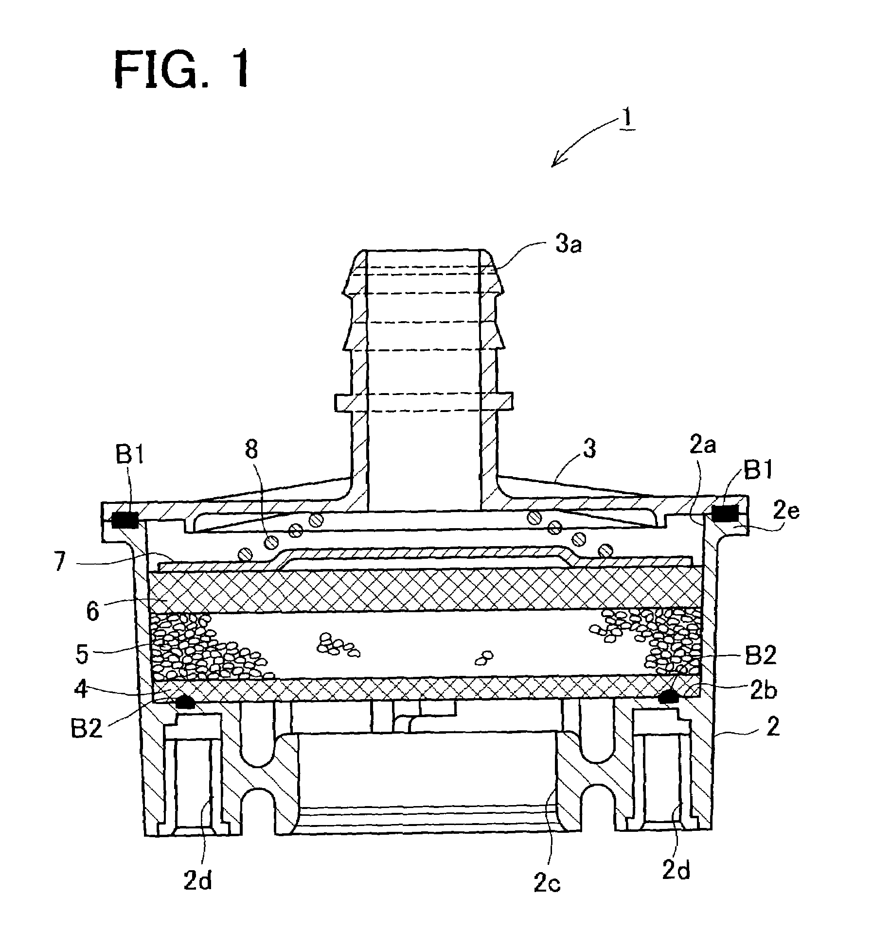
[0069]Next, explanation is made on a second embodiment of the laser welding method of the present invention, which is adopted to manufacture a canister.

[0070]It is to be noted that like elements in each of the following embodiments to those in the first embodiment are given like numerals and the explanation thereof is omitted. The following embodiments are explained with a focus on differences from the first embodiment.

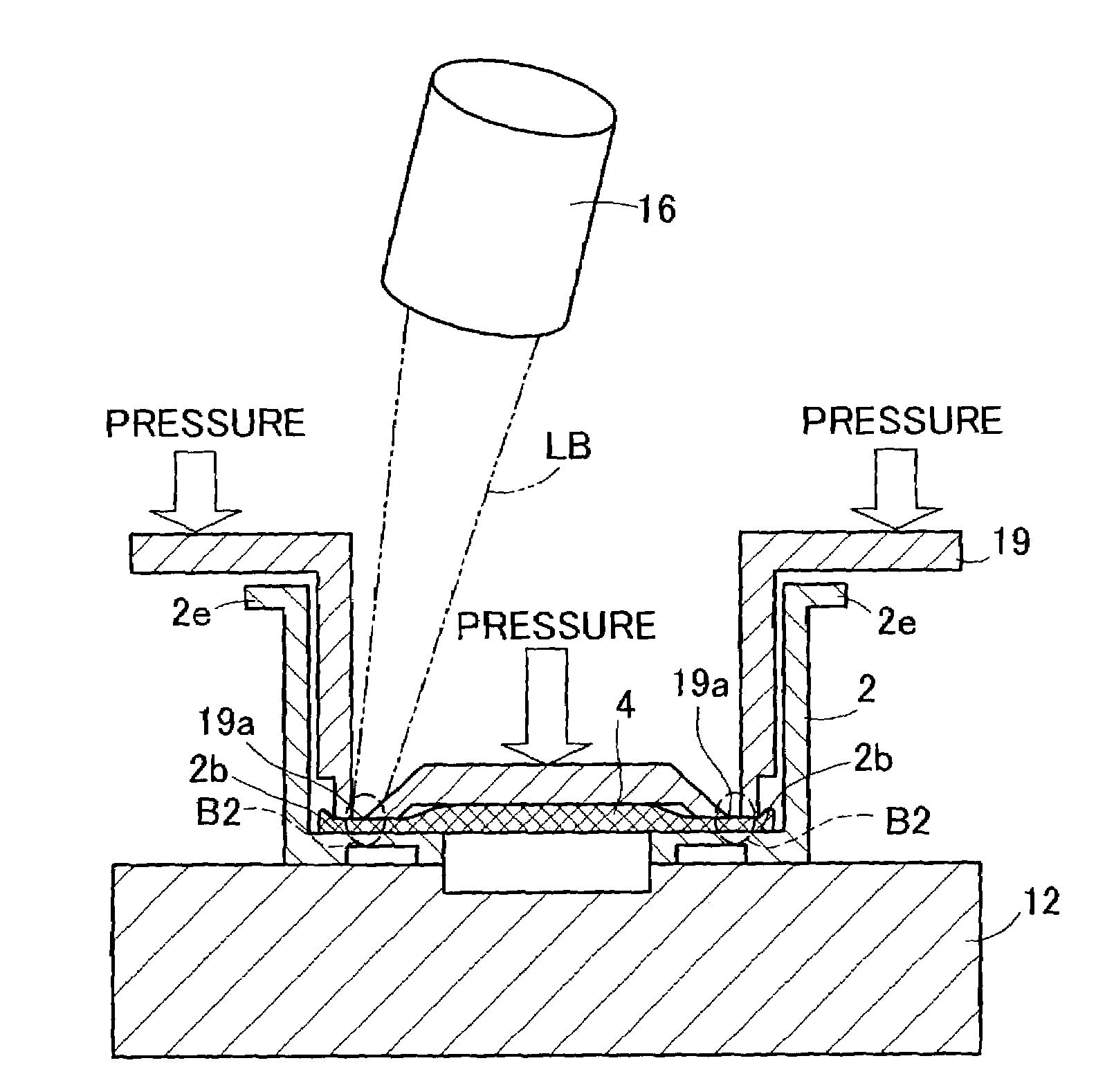
[0071]A different point of this second embodiment from the first embodiment in relation to the laser welding of the case 2 and the first filter 4 is in that a protrusion 2f is provided on the surface of the inside shoulder 2b of the case 2 in correspondence with the welding portion B2 of the first filter 4 as shown in FIG. 14.

[0072]More specifically, in a step of increasing the fiber density of the first filter 4 according to the laser welding method in the second embodiment, the periphery of the welding portion B2 is pressurized and compresse...

third embodiment

[0074][Third Embodiment]

[0075]Next, explanation is made on a third embodiment of the laser welding method of the present invention, which is adopted to manufacture a canister.

[0076]A different point of this third embodiment from the first and second embodiments in relation to the laser welding of the case 2 and the first filter 4 is in that a groove 2g is provided in the case 2 at a corner of the inside shoulder 2b in correspondence with the welding portion B2 of the filter 4 as shown in FIG. 15 and the peripheral edge of the first filter 4 is wedged in the groove 2g. More specifically, in a step of increasing the fiber density of the first filter 4 in the laser welding method in the third embodiment, the welding portion B2 and its periphery are inserted in a tucked state into the groove 2g of the inside shoulder 2b of the case 2 so that the welding portion B2 and its periphery are compressed inside the groove 2g.

[0077]In the third embodiment, since the welding portion B2 and its p...


PUM

PropertyMeasurementUnit
melting pointaaaaaaaaaa
diameteraaaaaaaaaa

Abstract

To weld a filter made of a laser beam-transmittable fiber material to a case made of a laser beam-nontransmittable resin material by a laser beam the filter is first placed on the case; subsequently, the filter is pressurized by a jig to increase the fiber density of a welding portion; and then the welding portion is irradiated by the laser beam. In the step of increasing the fiber density, a periphery of the welding portion is pressurized by the jig to increase the fiber density of the filter in a larger area than the welding portion. Accordingly, the laser beam transmitting through the filter melts a part of the case, and the melted resin material permeates through gaps between the fibers constituting the filter, thereby welding the welding portion to the case.

Description

BACKGROUND OF THE INVENTION[0001]1. Field of the Invention[0002]The present invention relates to a laser welding method for welding a fiber filter to a resin base member by a laser beam.[0003]2. Description of Related Art[0004]Some of conventional methods for welding a nonwoven filter made of fibers to a base member made of resin are disclosed in, for example, Japanese patent unexamined publications No. Hei 8-229312 and No. 2000-186635. These welding methods include a first step of placing a nonwoven filter made of polyester fibers onto a base member made of nylon (trade name), a second step of partially melting the base member, thereby allowing the melted material to permeate through the gaps between the fibers constituting the filter to weld the filter to the base member.[0005]Each related art mentioned above adopts an ultrasonic welding method or a vibrational friction welding method. For instance, in the ultrasonic welding method, an ultrasonic oscillator is disposed near a filt...

Claims


Application Information

Patent Timeline
Patent Type & Authority Patents(United States)
IPC IPC(8): B29C65/16B23K26/00F02M25/08B01D29/01B23K26/21B29C35/08B29C65/00B29K105/08
CPCB01D29/012B29C65/1696B29C65/1635B29C65/1687B29C65/169B29C65/7841B29C66/022B29C66/7485B29C66/80B29C66/53461B29C66/61B01D29/01B29C65/1612B29C65/1616B29C65/1674B29C66/303B29C66/5412B29C66/863B29C2035/0822B29K2067/00B29K2077/00B29L2031/14B29C65/08B29C65/1654B29C65/00B29C66/112B29C66/131B29C66/30325B29C66/71B29C66/712B29C66/7294B29C66/7392B29C66/8242B29C66/8322
Inventor SAKAI, TOMOHIROHIRATA, MASAMIFUKAYA, KANEHIRONAKAMURA, HIDEO
Owner AISAN IND CO LTD
Why Eureka
Try Eureka