Temperature sensor

a temperature sensor and sensor technology, applied in the field of temperature sensors, can solve the problems of the electrode wire breakage of the temperature sensor element, and achieve the effects of excellent weldability, good welding strength, and excellent resistance to load

Active Publication Date: 2009-12-31
NGK SPARK PLUG CO LTD
View PDF12 Cites 33 Cited by
  • Summary
  • Abstract
  • Description
  • Claims
  • Application Information

AI Technical Summary

Benefits of technology

[0023]As mentioned previously, when such temperature sensor including a ceramic filler is subjected to rapid cooling, the bottom portion of the enclosing member presses the front end of the temperature-sensing portion (temperature-sensing element) via the filler, thereby imposing a load on the weld zones between the signal wires and the electrode wires of the temperature-sensing element. However, according to the present invention, the electrode wires are formed of a material prepared by adding strontium to platinum or a platinum alloy and are welded to the signal wires in an overlapping condition. Thus, as compared with a conventional sensor in which the electrode wires formed of a dispersion-strengthened platinum material in which zirconia, yttria, or a like oxide is added are welded to the signal wires, the temperature sensor of the present invention exhibits excellent weldability and good welding strength in welding of the electrode wires to the signal wires. Accordingly, even when a load is imposed on the weld zones as a result of rapid cooling of the temperature sensor, the weld zones exhibit excellent resistance to the load. Thus, coupled with enhanced strength of the electrode wires, the occurrence of weld zone fractures can be restrained.

Problems solved by technology

However, use in an environment exposed to such strong vibrations gives rise to a problem of breakage of the electrode wires of the temperature-sensing element due to the vibrations imparted to the temperature sensor.

Method used


Image

  • Temperature sensor
  • Temperature sensor
  • Temperature sensor

Examples


second embodiment

[0068]The present invention is not limited to the above-described embodiment, but may be embodied in various other forms without departing from the gist of the invention.

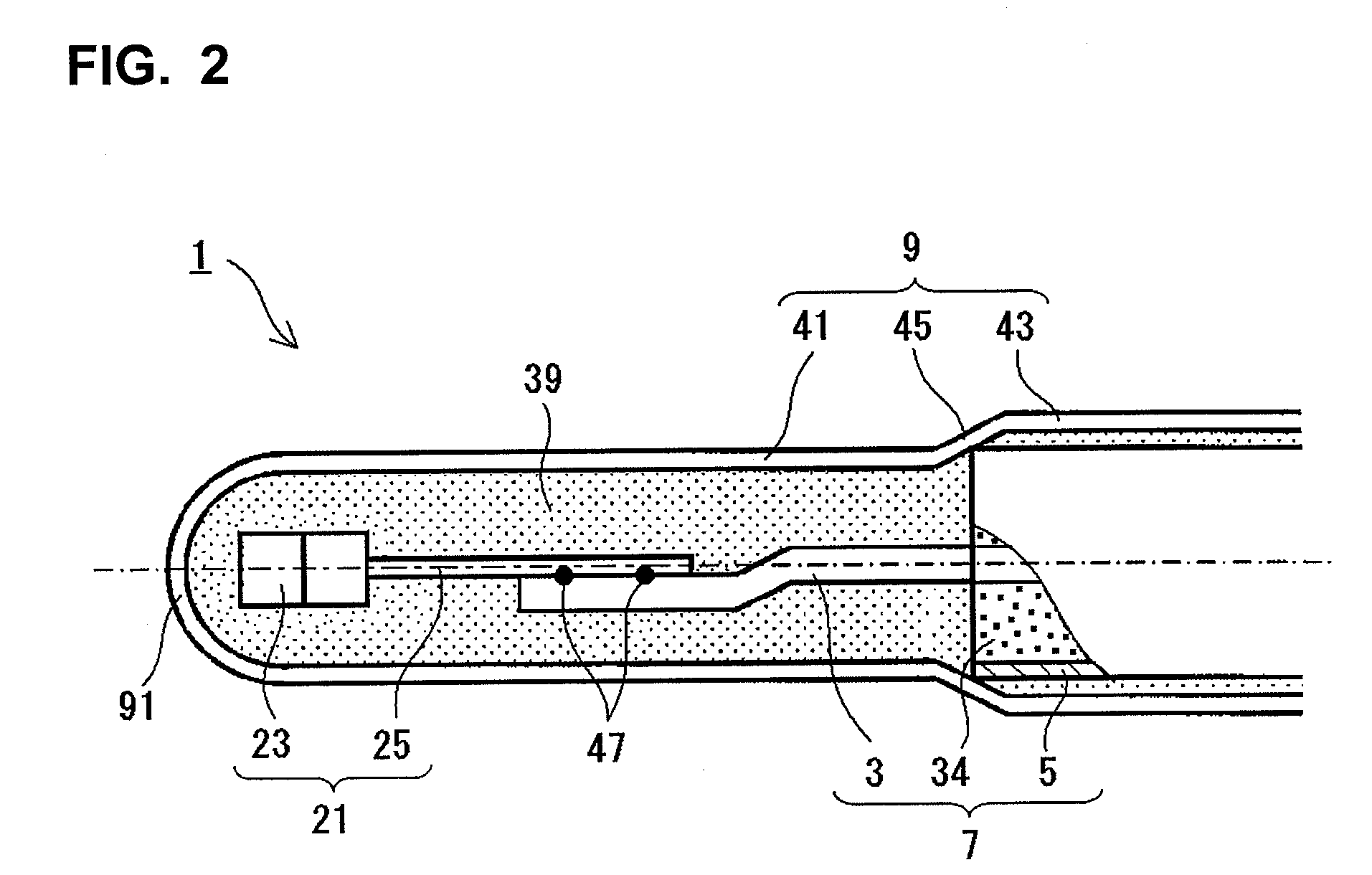
[0069]For example, the above-described embodiment employs a configuration in which cement 39 is charged into metal tube 9. However, a configuration in which cement 39 is not charged may be employed.

[0070]The temperature sensor 1 of the above-described embodiment uses the thermistor element as a temperature-sensing element. However, the temperature-sensing element may be configured such that the electrode wires are connected to a platinum resistor provided in a ceramic substrate and serve as a temperature-sensing portion. The temperature sensor 1 is described while mentioning the electrode wires 25 formed of a material prepared by adding strontium to platinum. However, the electrode wires may be formed of a material prepared by adding strontium to a platinum alloy (e.g., platinum-rhodium alloy, platinum-iridium alloy...


PUM

PropertyMeasurementUnit
mean grain sizeaaaaaaaaaa
mean aspect ratioaaaaaaaaaa
melting pointsaaaaaaaaaa

Abstract

In a temperature sensor (1), a pair of electrode wires (25) of a thermistor element (21) are formed of a material prepared by adding strontium to platinum or a platinum alloy and without addition of zirconia or a like oxide. Rear end portions of the electrode wires (25) formed of the above-mentioned material and front end portions of sheath core wires (3) are laser-welded to one another in an overlapping condition.

Description

BACKGROUND OF THE INVENTION[0001]1. Field of the Invention[0002]The present invention relates to a temperature sensor having a temperature-sensing element, which has a temperature-sensing portion, such as a thermistor portion made of a thermistor material, or a platinum resistor, and is used to detect the temperature of an object of measurement. Particularly, the present invention relates to a temperature sensor preferably used to detect the temperature of an object of measurement, such as exhaust gas, in an environment exposed to vehicle vibration.[0003]2. Description of the Related Art[0004]Conventionally, a temperature sensor is known which has a temperature-sensing element and signal wires, the temperature-sensing element being composed of a thermistor portion and electrode wires extending from the thermistor portion where the electrode wires and the signal wires are welded (e.g., laser-welded) to one another in an overlapping condition. In the thus-configured temperature sensor...

Claims


Application Information

Patent Timeline
Patent Type & Authority Applications(United States)
IPC IPC(8): G01K7/22
CPCG01K7/22G01K1/08
Inventor YOKOI, HITOSHIITO, MASAMICHICHOSOKABE, TAKAAKINISHI, MASAHIKO
Owner NGK SPARK PLUG CO LTD
Why Eureka
Try Eureka