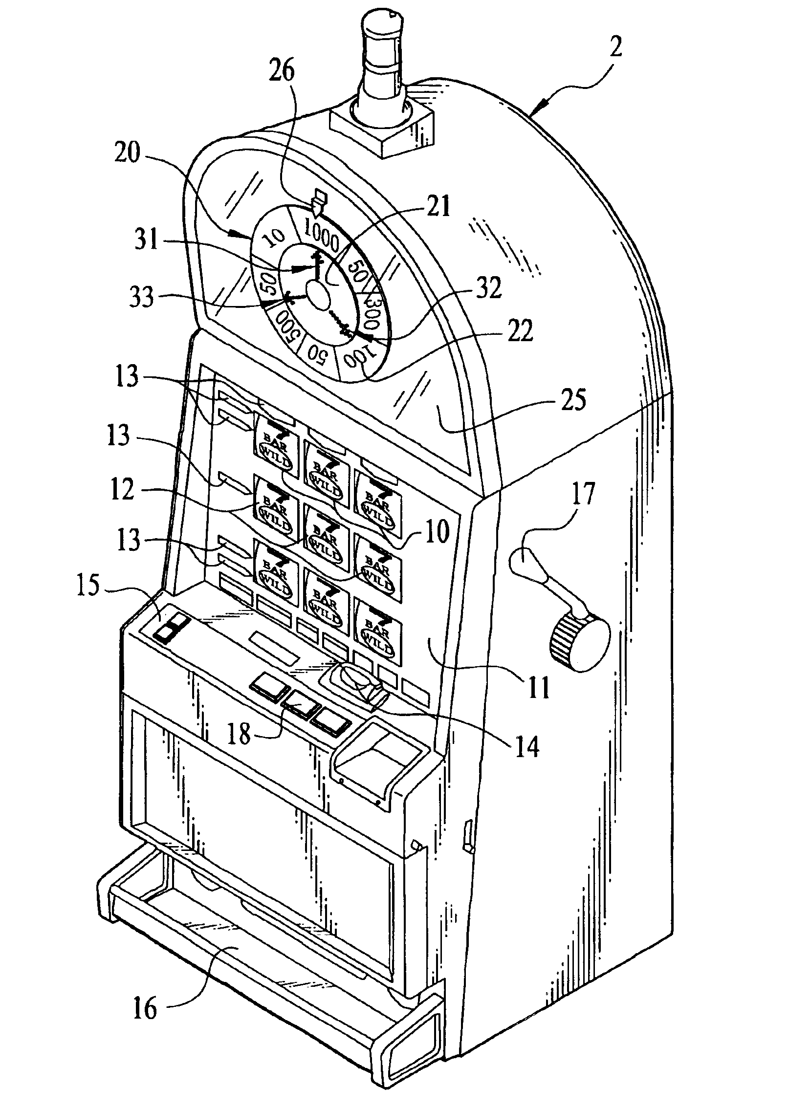
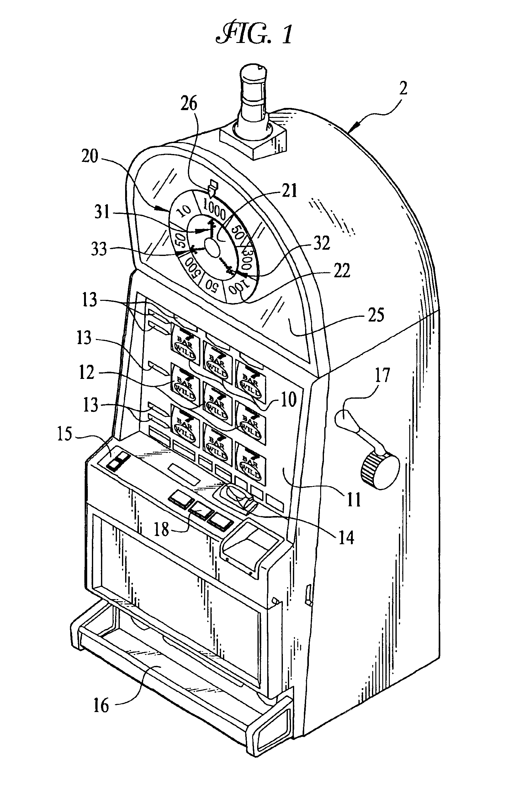
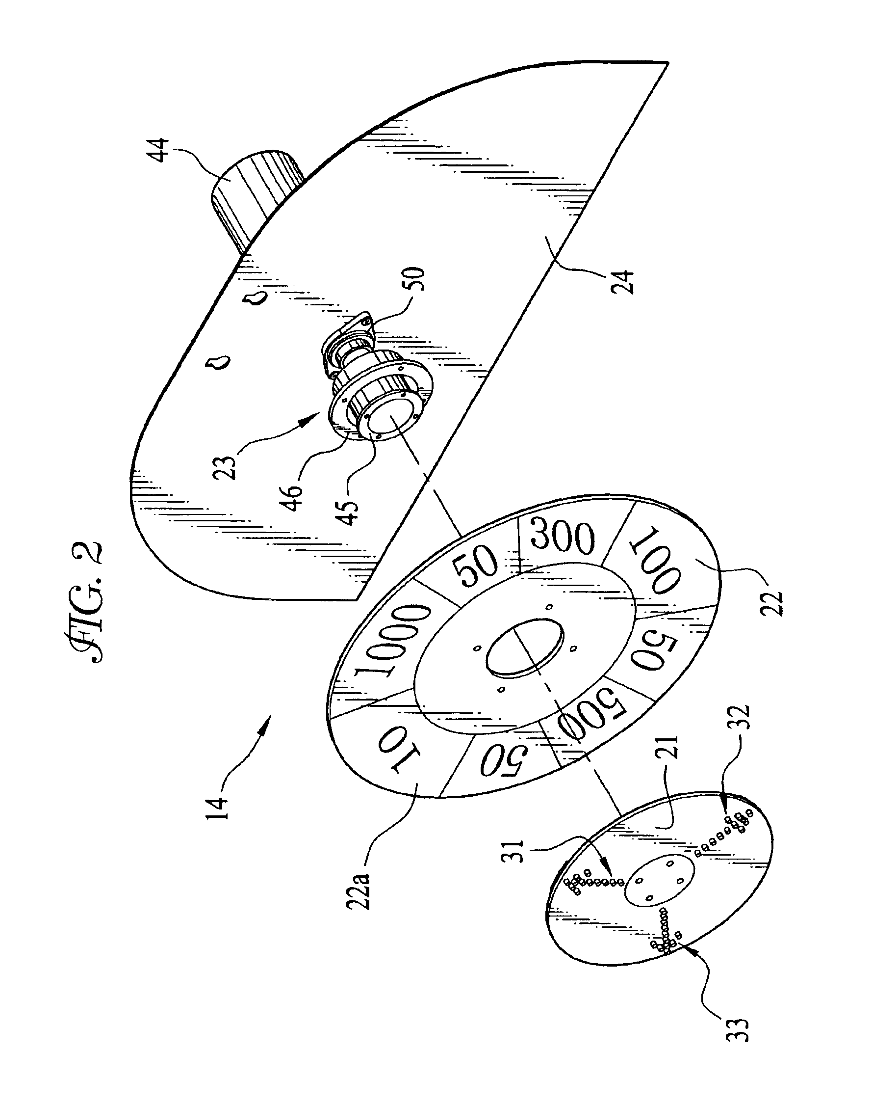
Symbol display device for game machine
a display device and game machine technology, applied in the field of symbols, can solve the problems that the symbol display device cannot provide various game types, and achieve the effect of improving the appeal effect of the player
- Summary
- Abstract
- Description
- Claims
- Application Information
AI Technical Summary
Benefits of technology
Problems solved by technology
Method used
Image
Examples
second embodiment
The present invention does not limit the above embodiment in which the first display plate 21 with the light emission parts and the second display plate 22 with the number symbols are individually rotated. FIG. 9 shows the second embodiment in which only a first display plate 63 with a light emission part 62, composed of LEDs 61, rotates clockwise (the direction shown by the arrow in the drawing). In this embodiment, a second display plate 60 with a symbol display part 60a is fixed. While the first display plate 63 rotates in the game, the light emission part 62 is lighted on and off to display the message or symbols by utilizing afterimage effect. After the first display plate 63 stops rotation, the amount of dividend coins is determined by lighting on or off the light emission part 62. If the light emission part 62 is kept the light on after the first display plate 63 stops rotation, the number indicated by the light emission part 62 represents the amount of the dividend coins. Fo...
third embodiment
In addition, the present invention may also be applied to a game machine that has plural display plates with display areas. shown in FIG. 11, the symbol display device has first, second and third display plates 70, 71 and 72. A light emission part 74, wherein LEDs 73 are provided, is in the front surface of the first display plate 70, while display areas 71a, 72a carrying number symbols are provided on the peripheries of the second and the third display plates 71, 72.
As shown in FIG. 11, on starting the game, the symbol display device starts its operation and rotates the first to third display plates. During the rotation, the LEDs 73 of the light emission parts 74 light on and off to display messages or symbols by utilizing afterimage effect. Then, the third display plate 72, the second display plate 71 and the first display plate 70 stop the rotation in the order mentioned. The winning type is determined in accordance with the symbol combination of the second and third display pla...
fourth embodiment
Though two display plates (first and second display plates) having different diameters are used in the above embodiment, the two display plates may have the same diameter as well. In the fourth embodiment shown in FIG. 13, the symbol display device is composed of a first display plate 81 and a second display plate 82, which have the same diameter. There is a display area 82a in the periphery of the second display plate 82. At least the part of the first display plate 81 overlapping with the display area 82a of the second display plate 82 (shown by the reference numerical 81a in the drawing) is made of a transparent material such as acrylic. At the front surface of the part 81a is provided with a light emission part 84 in which plural LEDs 83 are arranged. As shown in FIG. 14, all LEDs 83 are used to show the symbols or messages by utilizing afterimage effect while the first display plate 81 is rotating. In FIG. 15, the light emission part 84 is divided into a first LED group 83a ove...
PUM
 Abstract
Description
Claims
Application Information
 - R&D
- Intellectual Property
- Life Sciences
- Materials
- Tech Scout
- Unparalleled Data Quality
- Higher Quality Content
- 60% Fewer Hallucinations
Browse by: Latest US Patents, China's latest patents, Technical Efficacy Thesaurus, Application Domain, Technology Topic, Popular Technical Reports.
© 2025 PatSnap. All rights reserved.Legal|Privacy policy|Modern Slavery Act Transparency Statement|Sitemap|About US| Contact US: help@patsnap.com


