
Attenuation apparatus for minimizing reflections of electromagnetic energy from an antenna disposed within a radome

Inactive Publication Date: 2005-02-15
THE BOEING CO
View PDF12 Cites 20 Cited by
  • Summary
  • Abstract
  • Description
  • Claims
  • Application Information

AI Technical Summary

Benefits of technology

The attenuation apparatus of the present invention can thus be used with a wide variety of antennas and does not require modifications to the aerodynamic shape of the radome, which is extremely important in maintaining a smooth aerodynamic profile for the radome.

Problems solved by technology

Non-mechanically scanned phased array antennas normally do not require a radome due to their low aerodynamic cross section.
An undesirable consequence of mounting the antenna within an aerodynamically shaped radome is the creation of reflections of electromagnetic energy caused by the radiated electromagnetic energy impinging the radome at angles other than normal to the interior surface of the radome.
However, as the angles of incidence increase from 70 to 90 degrees, reflection losses increase significantly.
The problem with reflected energy is also acute when the main beam from the mechanically scanned antenna is scanned along an axis which is close to parallel to the exterior of the fuselage of the aircraft.
Reflected energy is highly undesirable as this energy can be directed into the skin of the aircraft, wherein the skin can act as an antenna to further radiate the energy towards other RF receivers or transceivers in the vicinity of the aircraft, and particularly transceivers located on the ground below the aircraft.
It is also undesirable for a communications system to have its high level radiated transmit power reflected back into the antenna aperture and into the low noise receiver.
Since the radome must have a highly aerodynamic shape, it becomes impossible to avoid the problem of reflections within the radome because at such angles as described above, the main beam radiated by the antenna will always be impinging the walls of the radome at angles that are not normal to the interior surface of the radome.

Method used


Image

  • Attenuation apparatus for minimizing reflections of electromagnetic energy from an antenna disposed within a radome
  • Attenuation apparatus for minimizing reflections of electromagnetic energy from an antenna disposed within a radome
  • Attenuation apparatus for minimizing reflections of electromagnetic energy from an antenna disposed within a radome

Examples


Embodiment Construction

The following description of the preferred embodiments is merely exemplary in nature and is in no way intended to limit the invention, its application, or uses.

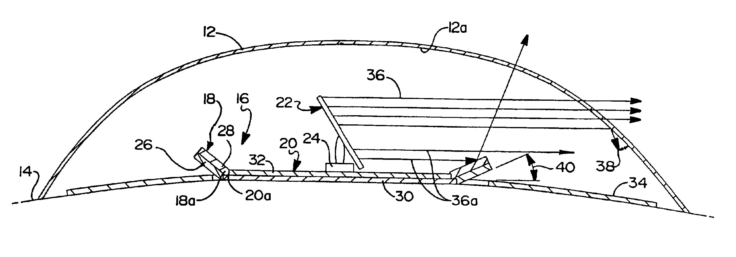
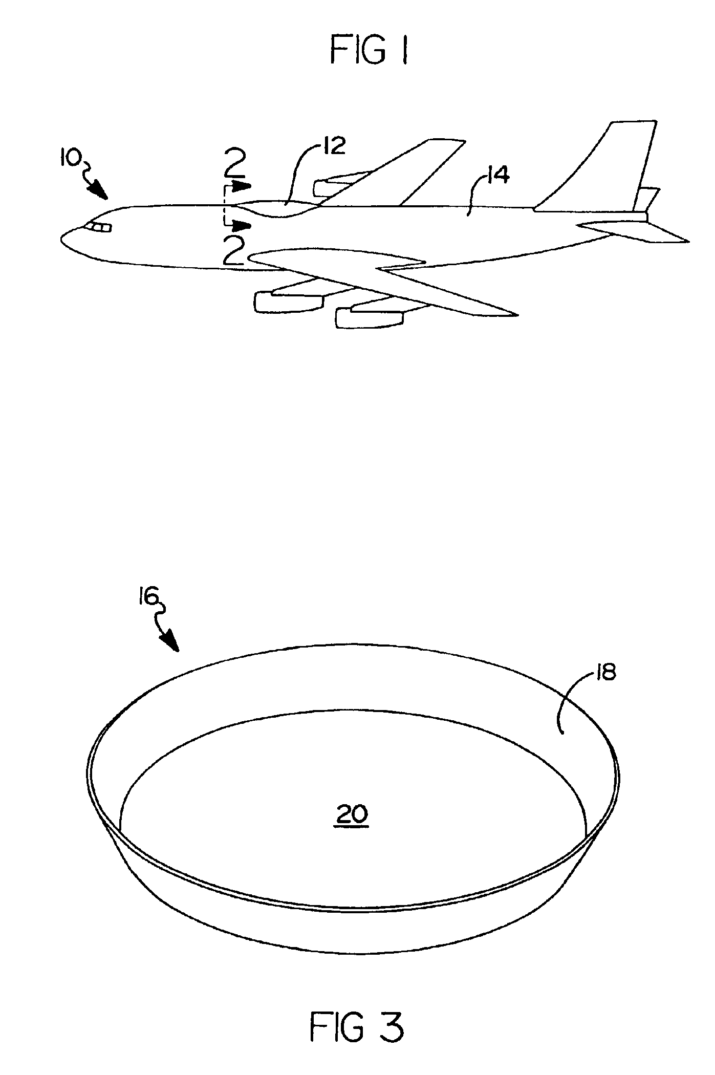
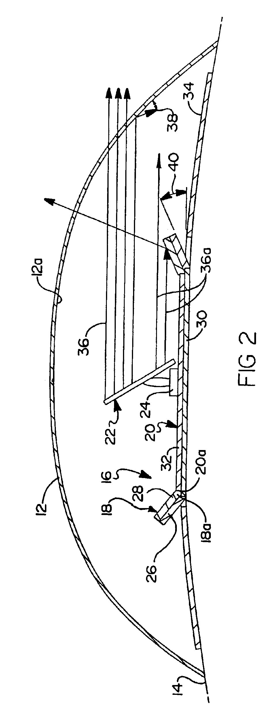
Referring to FIG. 1, there is shown an aircraft 10 upon which a radome 12 is mounted. It will be appreciated immediately, however, that while an aircraft has been illustrated as the mobile platform with which the present invention is to be used, that the present invention can be adapted for use with virtually any other form of mobile platform such as a bus, train, ship or any other form of vehicle or structure that requires the use of an aerodynamic radome.

The radome 12 typically has an overall length which is about seven to ten times that of its height to provide a highly aerodynamic profile. The highly aerodynamic profile is extremely important with commercial aircraft to minimize wind drag and therefore minimize the effect of the radome 12 on the performance of the aircraft and its fuel economy. The radome 12 may be mounte...


PUM


Abstract

An attenuation device for use under a radome disposed on a mobile platform such as an aircraft for reflecting a portion of the electromagnetic energy radiated by an antenna disposed under the radome such that the reflected portion of energy impinges the radome at an angle normal thereto, thereby reducing or eliminating further reflections of the reflected portion of energy within the radome toward the mobile platform. In one embodiment the radome includes a base covered with a radar absorbing material (RAM). In another embodiment the radome includes a curved base adapted to match the mobile platform surface curvature on which the attenuation apparatus is mounted. In a further embodiment, RAM is disposed on an exterior surface of the mobile platform under the radome. In still another embodiment, the base is formed of an attenuating transverse magnetic TM wave corrugated plate.

Description

FIELD OF THE INVENTIONThis invention relates to antenna assemblies, and more particularly to an attenuation apparatus and / or a radar absorbing material for use with an antenna disposed within a radome on a mobile platform such as an aircraft for reducing reflections of electromagnetic energy within the radome.BACKGROUND OF THE INVENTIONTransmit and receive antennas are now being used on the exterior surfaces of commercial aircraft to provide broadband interconnectivity with ground based stations via one or more satellite-based transponders. Such antennas are often electronically scanned phased array antennas; mechanically augmented phased array antennas; mechanically scanned reflector antennas summarized herein as antennas from the group including single reflector antennas, reflector arrays or planar arrays configured in a planar or elliptical shape; or other forms of antennas which are disposed on an exterior surface of the fuselage of the aircraft. Except for non-mechanically scan...

Claims


Application Information

Patent Timeline
IPC IPC(8): H01Q1/27H01Q1/52H01Q1/28H01Q1/00H01Q1/42H01Q19/10H01Q1/32
CPCH01Q1/28H01Q1/32H01Q19/10H01Q1/526H01Q1/421B61L15/0027
Inventor DESARGANT, GLENN J.BIEN, ALBERT LOUIS
Owner THE BOEING CO
Learn More