Eureka AIR delivers breakthrough ideas for toughest innovation challenges, trusted by R&D personnel around the world.

Cable assembly with internal circuit modules

Inactive Publication Date: 2005-02-22
HON HAI PRECISION IND CO LTD
View PDF10 Cites 20 Cited by
  • Summary
  • Abstract
  • Description
  • Claims
  • Application Information

AI Technical Summary

Benefits of technology

It is another object of the present invention to provide a cable assembly transmitting different signals therethrough.

Problems solved by technology

However, the cable and wafer subassembly are retained in the housing by securing the housing halves together through bolts and nuts, thereby complicating the assemblage of the cable assembly.
Furthermore, an engagement of the housing halves is easy to become loose due to vibration during the transportation and other matters, whereby the cable and the wafer subassembly cannot be stably retained in the housing.
Thus, an electrical connection is adversely affected between the cable assembly and a complementary connector.
However, the modules may be pulled back with regard to the housing, thereby adversely affecting an electrical engagement when the cable assembly mates with the complementary connector again.
Furthermore, an additional device is employed to bind the cables together, thereby increasing the cost of the production.
The patents mentioned above do not satisfy this demand.

Method used


Image

  • Cable assembly with internal circuit modules
  • Cable assembly with internal circuit modules
  • Cable assembly with internal circuit modules

Examples


Embodiment Construction

Reference will now be made to the drawing figures to describe the present invention in detail.

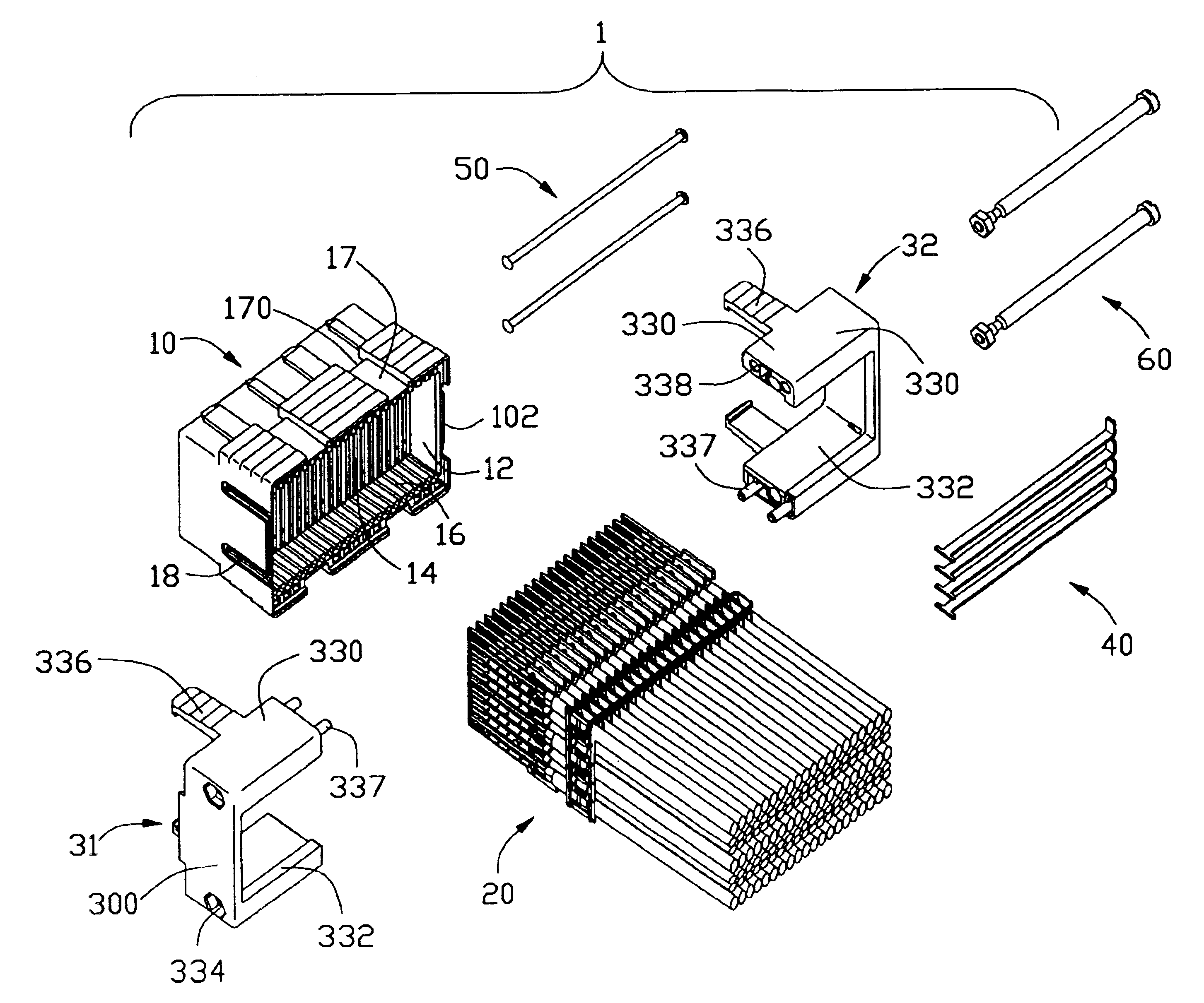
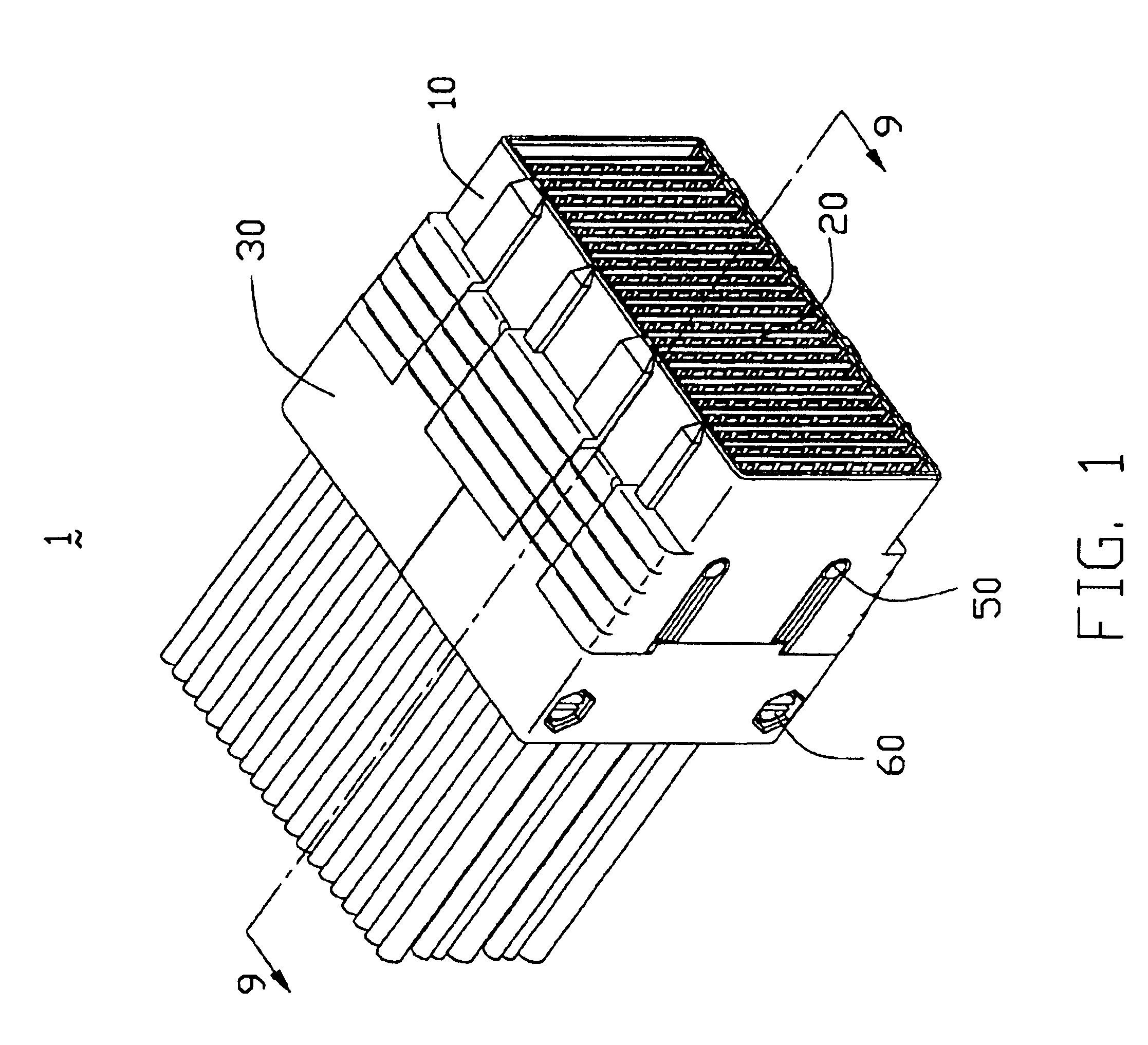
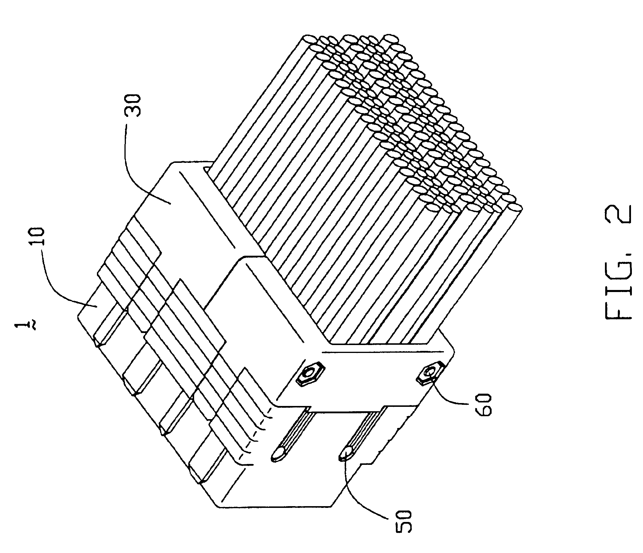
With reference to FIGS. 1 and 2, a cable assembly 1 in accordance with the present invention comprises a front insulating housing 10, a plurality of circuit modules 20 received in the front insulating housing 10, and a two-piece rear cover 30 together engaged with the front insulating housing 10 for retaining the circuit modules 20.

Referring to FIGS. 3 and 4, the front housing 10 is generally in a rectangular shape. The housing 10 has a front mating port 111 in a front mating face 100 thereof which faces a complementary connector (not shown) and a rear chamber 12 in a rear face 102 thereof. The housing 10 defines a plurality of parallel channels 14 extending in a front-to-back direction communicating with the front mating port 11 and the rear chamber 12 and a plurality of grooves 16 which are aligned with the channels 14. The housing 10 further defines a plurality of recesses 17 respectivel...


PUM


Abstract

A cable assemble (1) for engaging a complementary connector includes an insulation housing (10), number of circuit modules (20) received in the housing, and a two-piece cover (30) cooperating with the housing for retaining the circuit modules. Each circuit module includes a circuit board (22) accommodated in the housing, a number of first cables (231) and second coaxial cables (232) electrically and mechanically connected to the circuit board. Each second cable includes a second conductive core (2320) soldered on one side of the circuit board, and a grounding plate (24) attached to an opposite side of the circuit board and electrically connecting with a metal braid (2322) covering the second conductive core of each second cable.

Description

BACKGROUND OF THE INVENTION1. Field of the InventionThe present invention generally relates to a cable assembly, and particularly to a cable assembly having a plurality of circuit boards for high speed signal transmission.2. Description of Related ArtWith the development of communication and computer technology, high density electrical connectors are desired to construct a plurality of signal transmitting paths between two electronic devices. Each of these electrical connectors provides a plurality of circuit boards to thereby achieve improved signal transmission of different electrical characteristics through the connector. Such high density electrical connectors, such as cable assemblies, are widely used in internal connecting systems of severs, routers and the like requiring high speed data processing and communication.U.S. Pat. No. 6,217,364, issued to Miskin et al., discloses a cable assembly including an insulating housing formed by a pair of substantially identical housing ha...

Claims


Application Information

Patent Timeline
IPC IPC(8): H01R13/66H01R12/16H01R12/00H01R13/514
CPCH01R13/514H01R23/688H01R13/6658H01R12/772H01R13/6587H01R13/6594H01R12/00
Inventor WU, JERRY
Owner HON HAI PRECISION IND CO LTD
Why Eureka
Eureka Blog
Learn More