Exercise device with integrated handle and stopping device

a technology of a stopper and an exercise device, which is applied in the direction of resistance force resistors, gymnastic exercise, therapy exercise, etc., can solve the problems of not always being able to travel to the gym, limiting such devices to being used to exercise only specific muscles or groups of muscles, and not being able to isolate and tone specific muscles, etc., to achieve the effect of quickly “pumping up” the muscles of the user and toning individual muscle groups of the user

Inactive Publication Date: 2005-03-01
MORTORANO MICHAEL PETER
View PDF15 Cites 45 Cited by
  • Summary
  • Abstract
  • Description
  • Claims
  • Application Information

AI Technical Summary

Benefits of technology

It is an object of the invention to provide an exercise device which is capable of toning individual muscle groups of a user, as well quickly “pumping up” the muscles of the user. Accordingly, the invention provides an exercise device which is useable in a variety of different positions, and adaptable to a variety of different exercises to meet such goals.

Problems solved by technology

Considering the work, school, and travel schedule of many individuals, it is not always possible to travel to the gym.
Although such exercises are good for maintaining overall conditioning, they lack the ability to isolate and tone specific muscles.
However, many elastic exercising devices provide only constant resistance, which limits such devices to being used to exercise only particular muscles or groups of muscles.
In addition, such devices fail to challenge a user as the user's strength increases.
However, such an arrangement cannot reliably maintain the length adjustment and resist the cord tension exerted by a strong user.
Further, if the strap were to fail and the loop were to be suddenly released while the device is in use and under tension, it would very likely injure the user.

Method used


Image

  • Exercise device with integrated handle and stopping device
  • Exercise device with integrated handle and stopping device
  • Exercise device with integrated handle and stopping device

Examples


Embodiment Construction

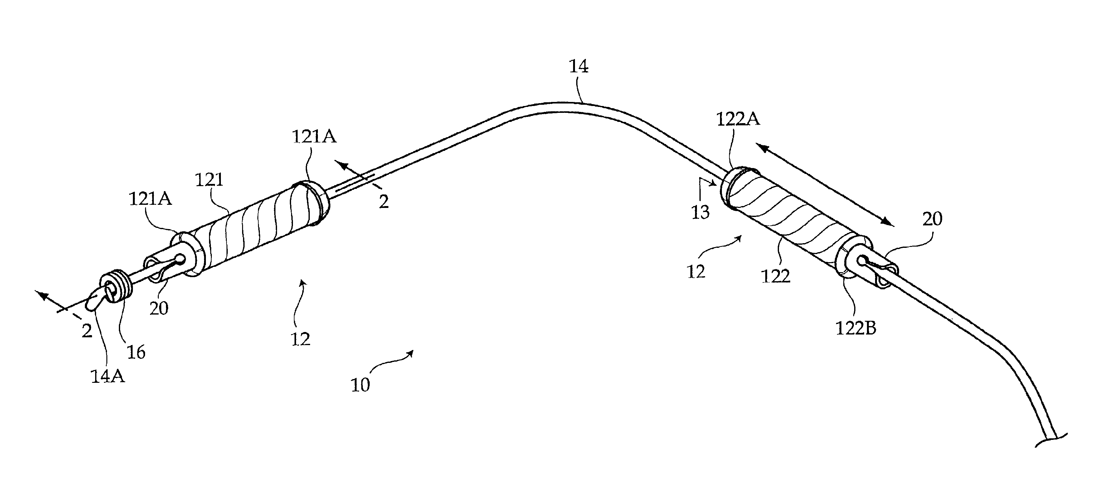
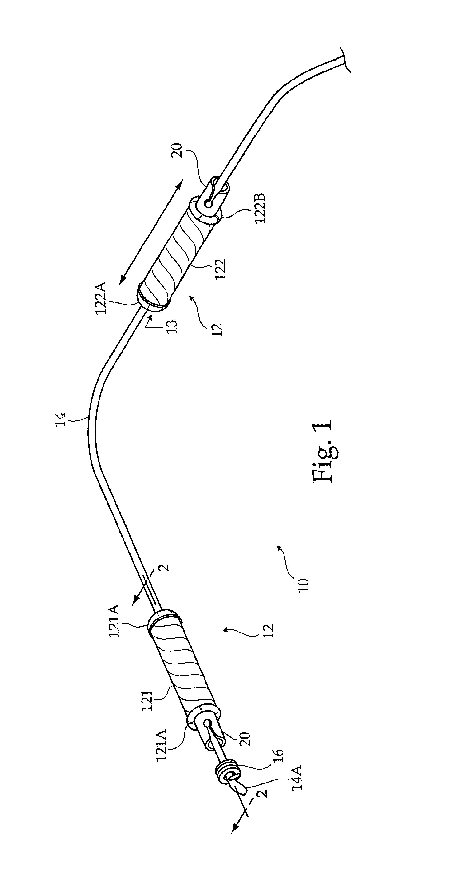
FIG. 1 illustrates an exercise device 10. The device 10 includes a pair of handles 12, each having a central longitudinal bore 13, and an elastic cord 14 which extends through the central longitudinal bore 13 of both handles 12. The elastic cord 14 has a relaxed diameter when substantially un-tensioned, and has a tendency to narrow when tensioned and stretched.

The handles 12 include a first handle 121 and a second handle 122. The elastic cord 14 has a fixed end 14A having a fixed coupling 16. The first handle 121 is located nearest to the fixed end 14A. The fixed coupling 16 may be employed to prevent the first handle 12 from moving past the fixed end 14A, and in effect limits longitudinal movement of the first handle 121 along the elastic cord 14. The first handle 121 and second handle 122 each have inner ends 121A and 122A, and outer ends 121B and 122B. The inner ends 121A and 122A face each other, while the outer ends 121A and 122B are fully opposite and face away from each other...


PUM


Abstract

An exercise device, having a pair of handles—namely a first handle and second handle, and an elastic cord extending through the handles. The elastic cord has a fixed end, the first handle located adjacent to the fixed end. The second handle located along the elastic cord further away from the fixed end than the first handle. The second handle can selectively slide freely along the elastic cord toward and away from the first handle. A stopping device is attached to at least one of the first handle and second handle. The stopping device is capable of fixing the position of its associated handle along the elastic cord so that the elastic cord may then be tensioned to allow exercises to be performed.

Description

BACKGROUND OF THE INVENTIONThe invention relates to an exercise device. More particularly, the invention relates to an exercise device which employs an elastic cord and a pair of handles to allow a variety of exercises to be performed, such that one or more of the handles has a stopping device which allows the user to selectively fix the position of the stopping device along the elastic cord so that the elastic cord can be tensioned between the two handles.For those who seek to maintain a toned physique, it is essential to keep a consistent exercise schedule in which exercises are performed that isolate target muscle groups. Since weight lifting and resistance based exercise machines are a typical part of such a regimen, frequent travel to the gym is a necessity.Considering the work, school, and travel schedule of many individuals, it is not always possible to travel to the gym. Rather than skip the workout altogether, many athletes will perform stretching exercises, push-ups, sit-u...

Claims


Application Information

Patent Timeline
Patent Type & Authority Patents(United States)
IPC IPC(8): A63B21/02A63B21/055A63B23/035A63B23/12
CPCA63B21/0004A63B21/00043A63B21/00185A63B21/0552A63B21/1434A63B21/1469A63B21/00069Y10S482/908A63B2225/09A63B21/0557A63B21/4017A63B21/4035
Inventor MORTORANO, MICHAEL PETER
Owner MORTORANO MICHAEL PETER
Why Eureka
Try Eureka