
Method and device for marking golf balls

a golf ball and marking technology, applied in the field of golf balls, can solve the problems of not being able to immediately determine the center of mass by sight, not being able to locate at the center of the sphere, and generally not being accurate,

Inactive Publication Date: 2005-03-08
SOSIN HOWARD
View PDF25 Cites 13 Cited by
  • Summary
  • Abstract
  • Description
  • Claims
  • Application Information

AI Technical Summary

Benefits of technology

The present invention provides a method and device for marking golf balls that allows for the placement of a putting directional indicator (PDI) along the dynamic axis of a ball. While golfers could use the device to mark individual balls after they have been purchased (i.e. after they already have marks on them from the manufacturer), in preferred embodiments, the PDI is applied at the m...

Problems solved by technology

However, at least two residual problems plague the golfer.
The first is an expected problem—he must not lose sight of his line as he steps up to execute the putt.
While this is a reasonable assumption, it is generally not an accurate one.
In particular, while most balls are virtually spherical (and those that are not can usually be weeded out by sight, or by mechanical means, e.g. dropping the ball through a ring repeatedly using different orientations for the ball), the center of mass cannot be immediately determined by sight and need not be located at the center of the sphere.
This is problematic as it means that a perfectly executed putt may not travel along its intended path.
Despite these devices and methods for marking golf balls and determining dynamic axes, significant problems remain.
The addition of aiming lines can make the ball appear busy and make it difficult to successfully utilize the aiming lines.
But since the manufacturer's markings do not account for the dynamic axis of the ball, clearly Dinh stencil will not be oriented optimally.
Many of the prior art devices and methods utilize non-permanent marking techniques, and all require significant work on the part of golfer.
Pelz's device has a number of problems, including: (1) it can handle only one ball at a time; each ball must be spun and marked individually; (2) the special marker for hand marking the golf ball can be easily misaligned by the user during the process of marking, resulting in an incorrectly drawn equator; (3) the ink used for the device is temporary and rubs off onto the club head at impact; (4) the device only provides for an equator; it is not possible to draw any other configuration; (5) the Pelz equator line must be placed in addition to any markings already on the ball; and (6) no matter how careful one is, it is difficult to avoid knocking the ball out of alignment while marking the ball.

Method used


Image

  • Method and device for marking golf balls
  • Method and device for marking golf balls
  • Method and device for marking golf balls

Examples


Embodiment Construction

Referring now to the figures of the drawing, the figures constitute a part of this specification and illustrate exemplary embodiments of the invention. It is to be understood that in some instances various aspects of the invention may be shown exaggerated or enlarged to facilitate an understanding of the invention.

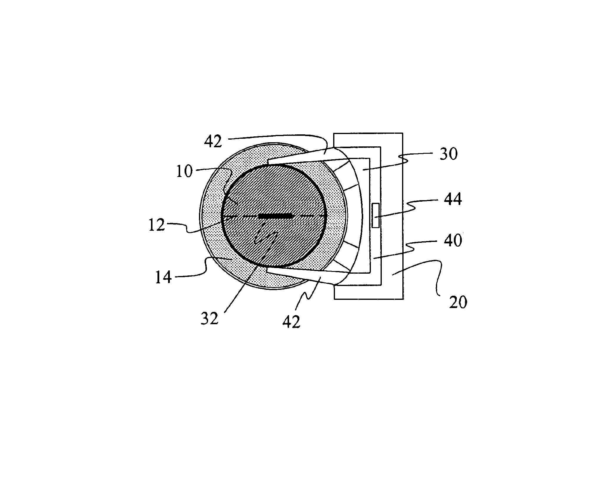
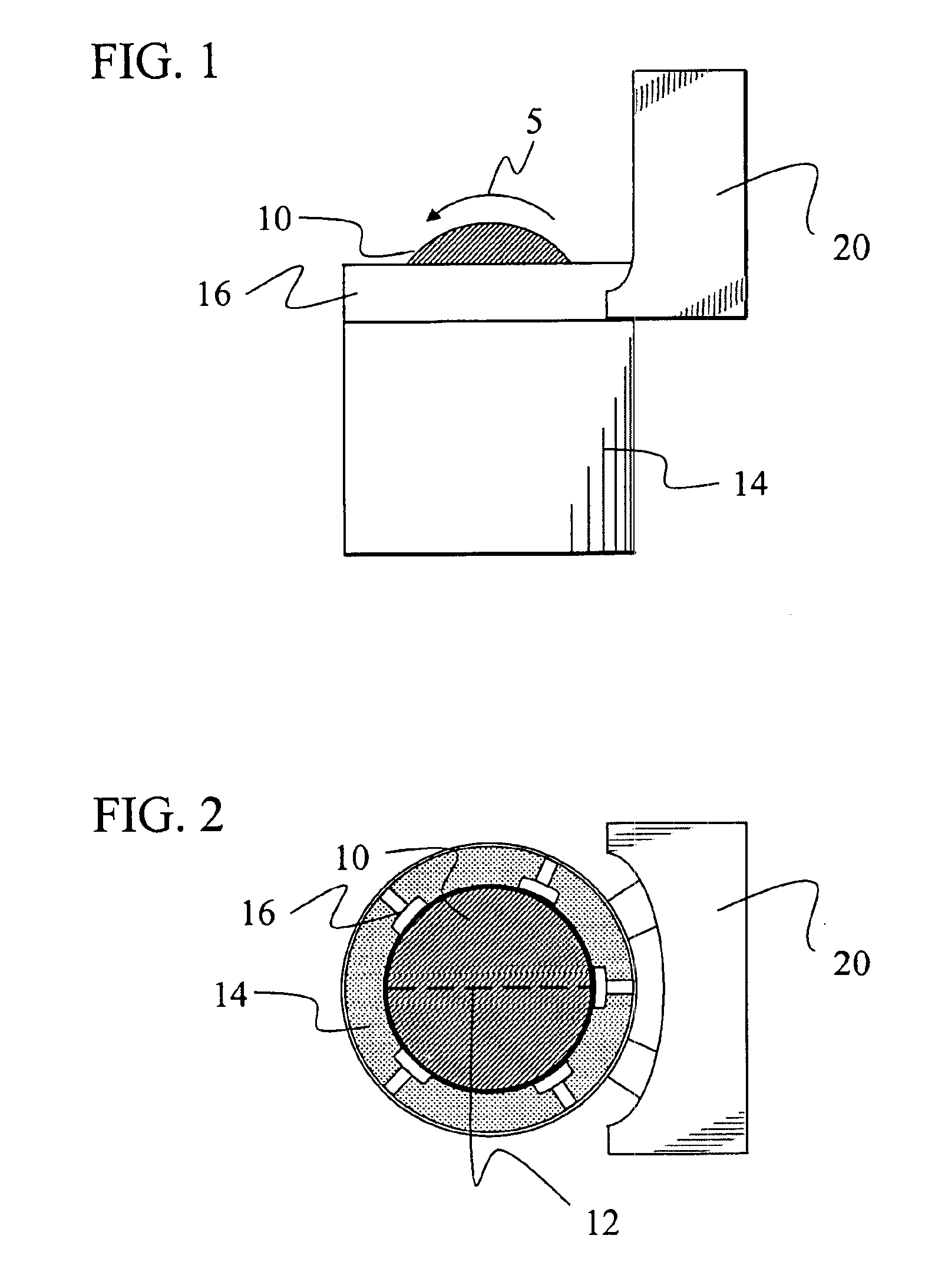
FIG. 1 is a side view of a dynamic axis locating device with a braking mechanism and marking device according to one embodiment of the invention. In one embodiment, the dynamic axis locating device 14 is a spinning device, for example, that utilizes a system to spin a ball 10 (e.g. a golf ball) in the direction shown by arrow 5 at high speed in order to locate the ball's dynamic axis. The ball is then quickly stopped in place by a braking mechanism 16 and held in a position such that the newly located dynamic axis can be marked by a putting directional indicator (PDI) marking device 20. In a preferred embodiment, the PDI mark is a permanent one, but alternatively, a PDI ma...


PUM


Abstract

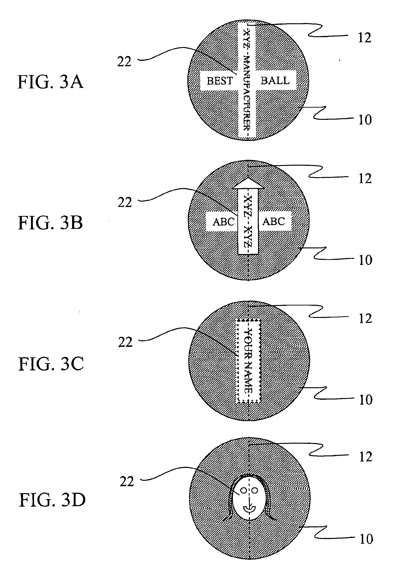
A method and device for marking golf balls that allows for the placement of a putting directional indicator (PDI) along the dynamic axis of a ball. While golfers could use the device to mark individual balls after they have been purchased (i.e. after they already have marks on them from the manufacturer), in preferred embodiments, the PDI is applied at the manufacturing stage and / or before the ball has other markings placed upon it. While the PDI could simply consist of one or more lines, in a preferred embodiment, the putting directional indicator may serve as an identifying mark for a manufacturer, distributor or consumer and may be designed to incorporate letters, words, symbols, short sentences, names, initials, numbers, images and photographs.

Description

FIELD OF THE INVENTIONThe present invention is directed to the field of golf balls and more particularly to a method and device for marking golf balls.BACKGROUND OF THE INVENTIONA golfer must consider many variables when facing a putt. These variables including the slope(s) of the green, the type, cut, dampness and grain of the grass, the distance of the putt, and the weather (i.e. wind, rain, etc.). Data on many of these variables are available to the observant golfer. An analysis of all variables leads to a simultaneous decision as to how hard (the “speed”) and in what direction (the “line”) to strike the ball. It would seem that “all” that remains is for the golfer to step up to the ball and putt it along his intended line at his intended speed.However, at least two residual problems plague the golfer. The first is an expected problem—he must not lose sight of his line as he steps up to execute the putt. The second is unexpected—the golfer in choosing the parameters of his putt t...

Claims


Application Information

Patent Timeline
IPC IPC(8): A63B45/02A63B45/00A63B37/00G01M1/26G01M1/00A63B47/00A63B69/36B41J2/44
CPCA63B37/0003A63B45/02G01M1/26A63B37/0022A63B47/008Y10S101/40A63B69/3658
Inventor SOSIN, HOWARD
Owner SOSIN HOWARD
Learn More