Rotary gas valve for pulsing a gas

Inactive Publication Date: 2005-03-22
APPLIED MATERIALS INC
View PDF79 Cites 108 Cited by
  • Summary
  • Abstract
  • Description
  • Claims
  • Application Information

AI Technical Summary

Problems solved by technology

Providing such pulses of gas using conventional solenoid or pneumatically operated valves have not proven desirable for this use due to insufficient responsiveness, i.e., long cycle times, failure to shut off cleanly

Method used


Image

  • Rotary gas valve for pulsing a gas
  • Rotary gas valve for pulsing a gas
  • Rotary gas valve for pulsing a gas

Examples


Embodiment Construction

been used, where possible, to designate identical elements that are common to the figures.

[0016]It is to be noted, however, that the appended drawings illustrate only typical embodiments of this invention and are therefore not to be considered limiting of its scope, for the invention may admit to other equally effective embodiments.

DETAILED DESCRIPTION

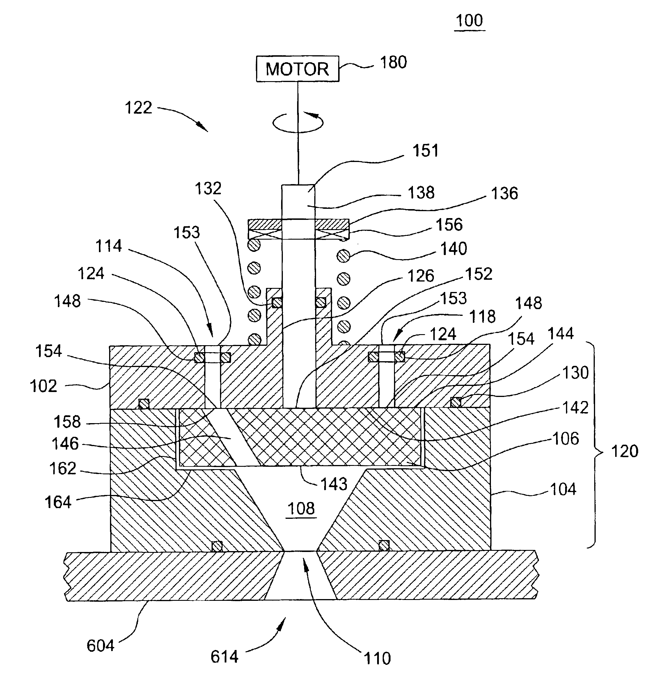
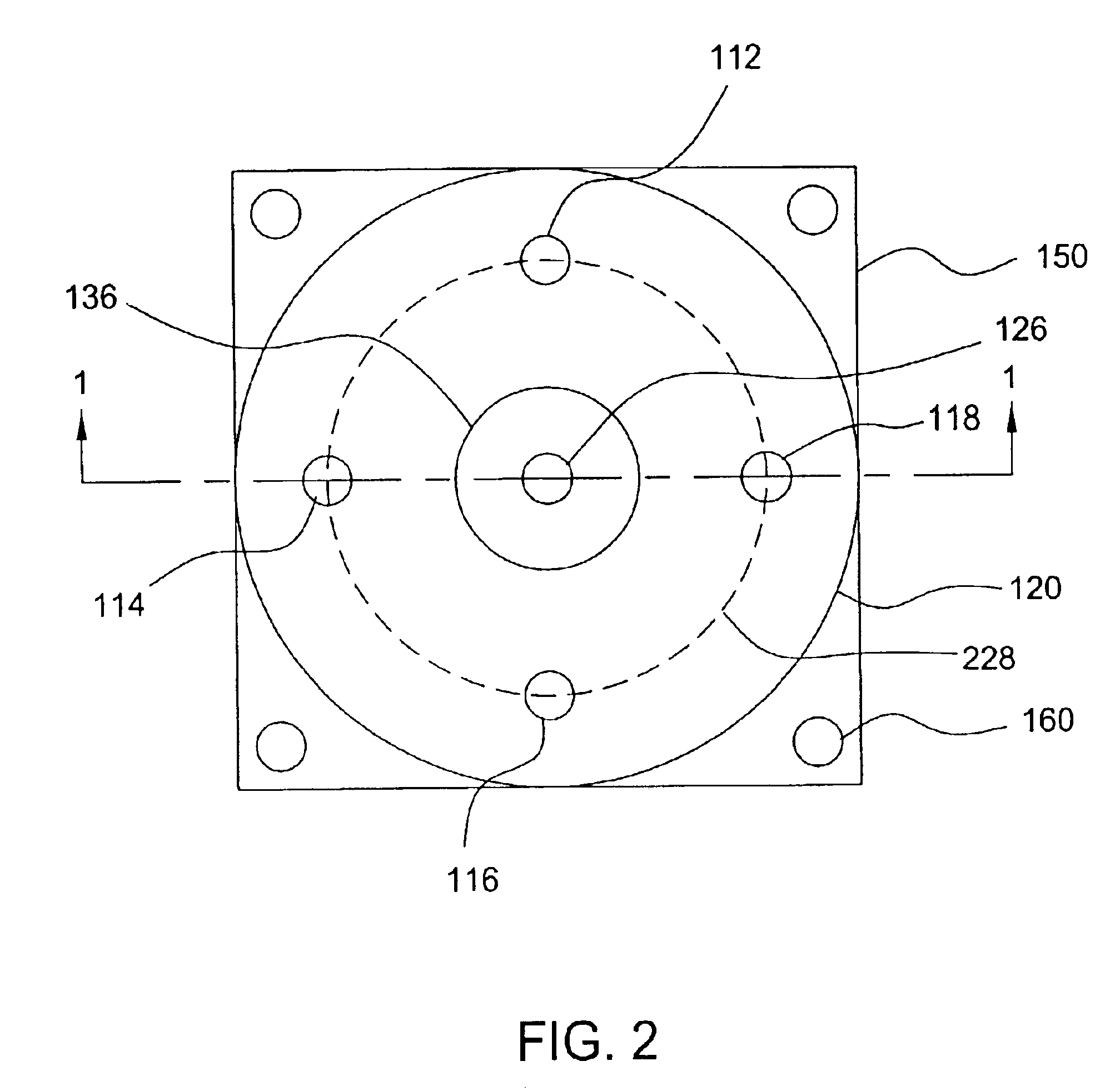
[0017]The present invention is a rotary gas valve for pulsing one or several gases (or gas mixtures) to form a sequence of pulses of the gas. Herein the terms gas and gas mixture are used interchangeably. The gases are supplied to the gas valve in a non-pulsed form, as a plurality of individual pressurized gases. The gas valve comprises a plurality of gas inlet ports and one gas outlet port. The gas inlet ports are sequentially engaged in fluid communication with the gas outlet port by a rotating selector disk. The selector disk comprises at least one timing slot. When the selector disk rotates, the timing slot periodically establishes...


PUM


Abstract

A gas valve for pulsing a gas comprises a housing having at least one inlet port, an outlet port, and a selector disk mounted in the housing and comprising at least one timing slot, wherein rotation of the selector disk periodically couples at least one inlet port to the outlet port through the timing slot.

Description

BACKGROUND OF THE INVENTION[0002]1. Field of the Invention[0003]The present invention generally relates to semiconductor substrate processing systems. More particularly, the present invention relates to a gas valve for pulsing of one or more gases used in a semiconductor substrate processing system.[0004]2. Description of the Related Art[0005]In cylindrical film processing, for example, atomic layer deposition, atomic layer etch or other repetitive, thin film deposition or etch process, it is desirable to provide rapid and precise cycling of process gases to improve the production worthiness of processing systems. In this regard, valves that may reliably inject small amounts of materials at rapid rates are needed. Some current and desired cylindrical layer deposition processes will require injection sequences wherein a single pulse may be as short as a few tens of milliseconds and be separated from an adjacent pulse by a few tens of milliseconds. Providing such pulses of gas using c...

Claims


Application Information

Patent Timeline
IPC IPC(8): F16K31/04F16K11/074F16K11/06
CPCF16K31/041F16K11/074Y10T137/0318Y10T137/86405
Inventor YUDOVSKY, JOSEPH
Owner APPLIED MATERIALS INC
Why Eureka
Try Eureka