Ceiling loudspeaker

Inactive Publication Date: 2005-03-22
LIU HUNG MING
View PDF3 Cites 19 Cited by
  • Summary
  • Abstract
  • Description
  • Claims
  • Application Information

AI Technical Summary

Benefits of technology

It is a primary object of the present invention to eliminate the aforementioned drawbacks and to provide a ceiling loudspeaker which includes upward and downward adjustable fixing pieces at sides of speaker housing which are fixed by butterfly screws on the speaker housing for installing the loudspeaker on th

Problems solved by technology

However, the aforementioned structure of the conventional ceiling loudspeaker has its drawbacks.
Besides, in assembly, the screw hole is uneasy to be aligned.
Therefore, the fixing seat 200 is of

Method used


Image

  • Ceiling loudspeaker
  • Ceiling loudspeaker
  • Ceiling loudspeaker

Examples


Example

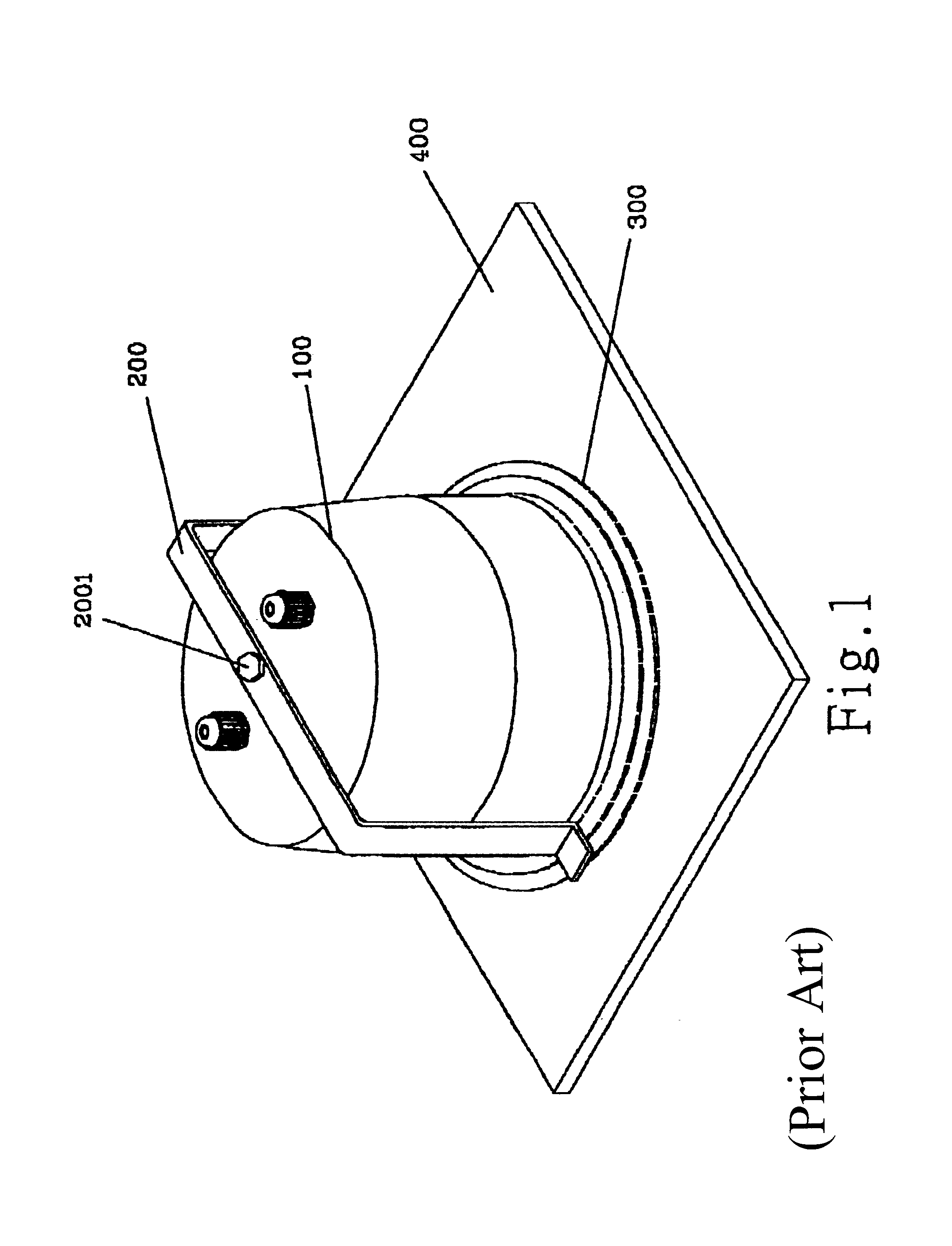
FIG. 1 shows a perspective assembly view of a conventional ceiling loudspeaker. The configuration and the disadvantages thereof have been shown above and won't be described more hereinafter.

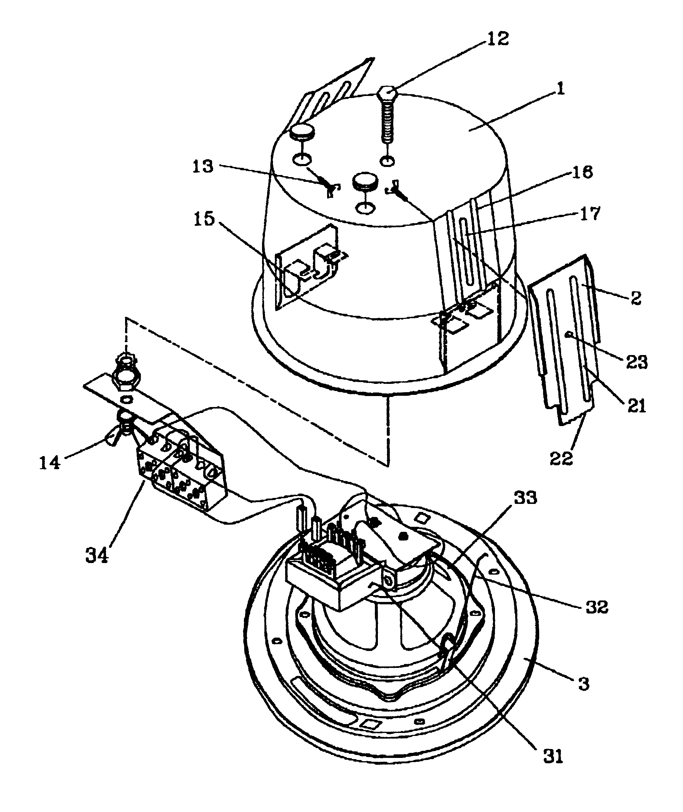
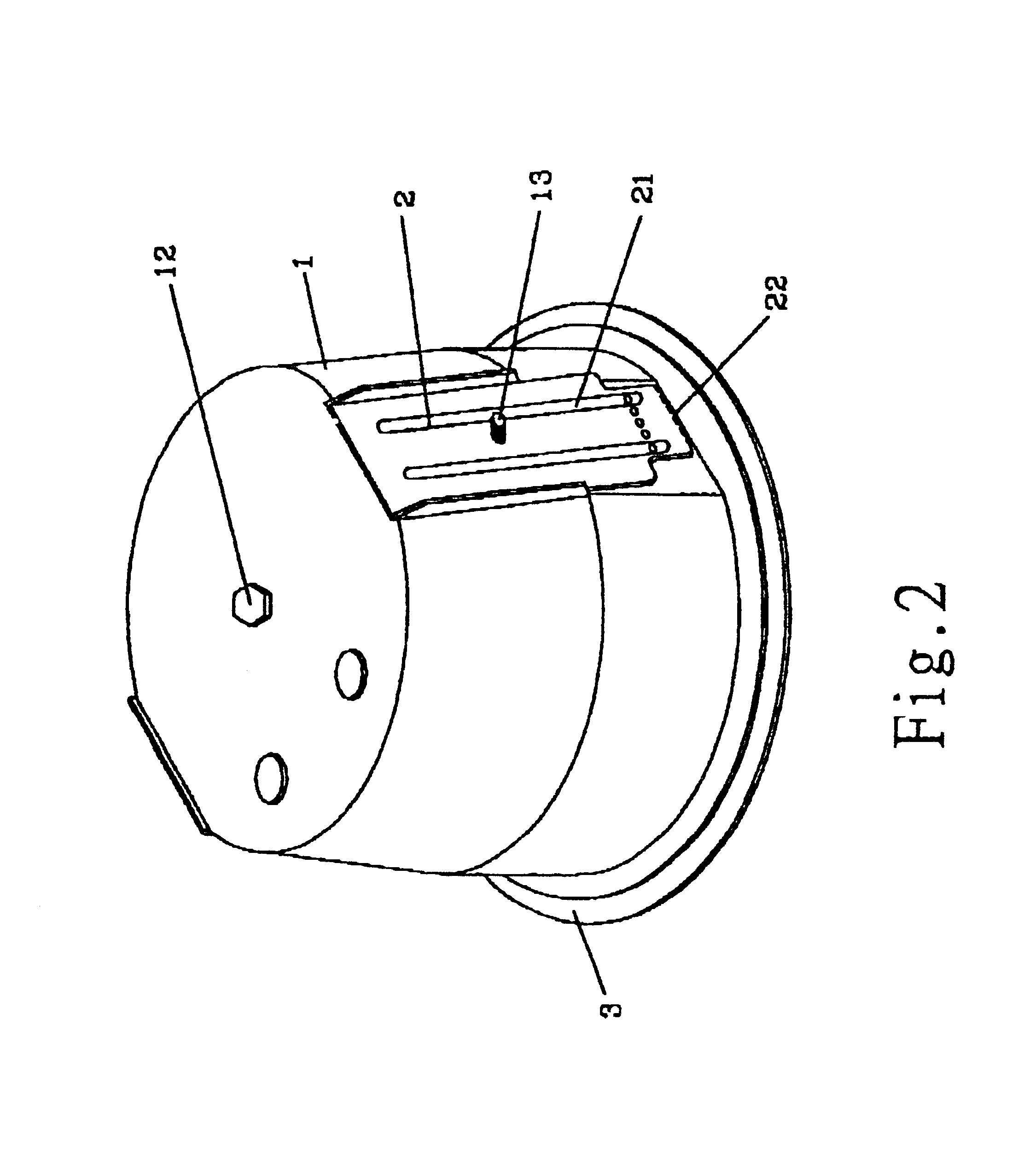
Referring to FIGS. 2 and 3, the ceiling loudspeaker in accordance with the present invention at least includes a housing 1, a plurality of fixing pieces 2 and a speaker seat 3. The housing 1 in shape of a hollow cylinder includes a screw 12 disposed at top thereof, a plurality of strip-type grooves 16 and slots 17 at outer sides thereof and a plurality of spring seats 15 at inner lower sides thereof. The fixing pieces 2 includes a plurality of grooves 21, thereby forming a plurality of ridges at corresponding position of the rear side thereof, zigzag projections 22 at bottom end thereof and a threaded hole 23 near the center thereof. The speaker seat 3 includes a plurality of projecting hooks 31 on each of which a V-shaped tension spring 32 is hooked while a speaker body 33 is mounted on the spea...


PUM


Abstract

The present invention relates to a ceiling loudspeaker, primarily including adjustable fixing pieces at sides of speaker housing for installing the loudspeaker on the ceiling in position. Besides, a plurality of hooks are fitted to the speaker set, and tension springs are connected to the hooks while the speaker seat is hooked by the tension springs on the spring seats of the housing. Accordingly, the ceiling loudspeaker is convenient in assembly and stable in connection.

Description

BACKGROUND OF THE INVENTION1. Field of the InventionThe present invention relates to a ceiling loudspeaker, and more particularly, to a loudspeaker on whose housing is provided with position-adjustable fixing pieces and spring seats hanging on a speaker seat while the speaker seat includes hooks and tension springs. Accordingly, the ceiling loudspeaker in accordance with the present invention is convenient in assembly and stable in connection.2. Description of the Prior ArtA conventional ceiling loudspeaker, as shown in FIG. 1, includes a fixing seat 200 on the ceiling while a housing 100 thereof passes through a through hole prearranged on the ceiling 400 and is then screwed on the fixing seat 200 of the housing 100 by a screw 2001 passing through a through hole prearranged at top of the housing 100. The housing 100 is locked on the ceiling 400 by means of the arrangement of the fixing seat 200. Thereafter, a speaker seat 300 is mounted at the inner side of the housing 100. Accordi...

Claims


Application Information

Patent Timeline
IPC IPC(8): H04R1/02
CPCH04R1/026H04R2201/021
Inventor LIU, HUNG-MING
Owner LIU HUNG MING
Why Eureka
Try Eureka