Multi-joint wrench

a multi-joint, wrench technology, applied in the direction of wrenches, screwdrivers, manufacturing tools, etc., can solve the problems of crooked space, inability to operate in limited space, and the wrench can be used in limited spa

Inactive Publication Date: 2005-04-12
CHEN TERENCE
View PDF5 Cites 49 Cited by
  • Summary
  • Abstract
  • Description
  • Claims
  • Application Information

AI Technical Summary

Benefits of technology

The primary objective of the present invention is to provide a wrench including a configuration that can adapt to limited and crooked space.
According to the present invention, a wrench includes a head, a first handle, a second handle and a retaining device. The first includes first and second end. The first end of the first handle is pivotally connected with the head about a first axis. The second handle is pivotally connected with the second end of the first handle about a second axis. The retaining device can retain the first handle in position relative to the head, and the second handle in position relative to the first handle.

Problems solved by technology

This conventional wrench can therefore be used in space that is limited and slightly bent; however, it cannot be operated in limited and crooked space.

Method used


Image

  • Multi-joint wrench
  • Multi-joint wrench
  • Multi-joint wrench

Examples


Embodiment Construction

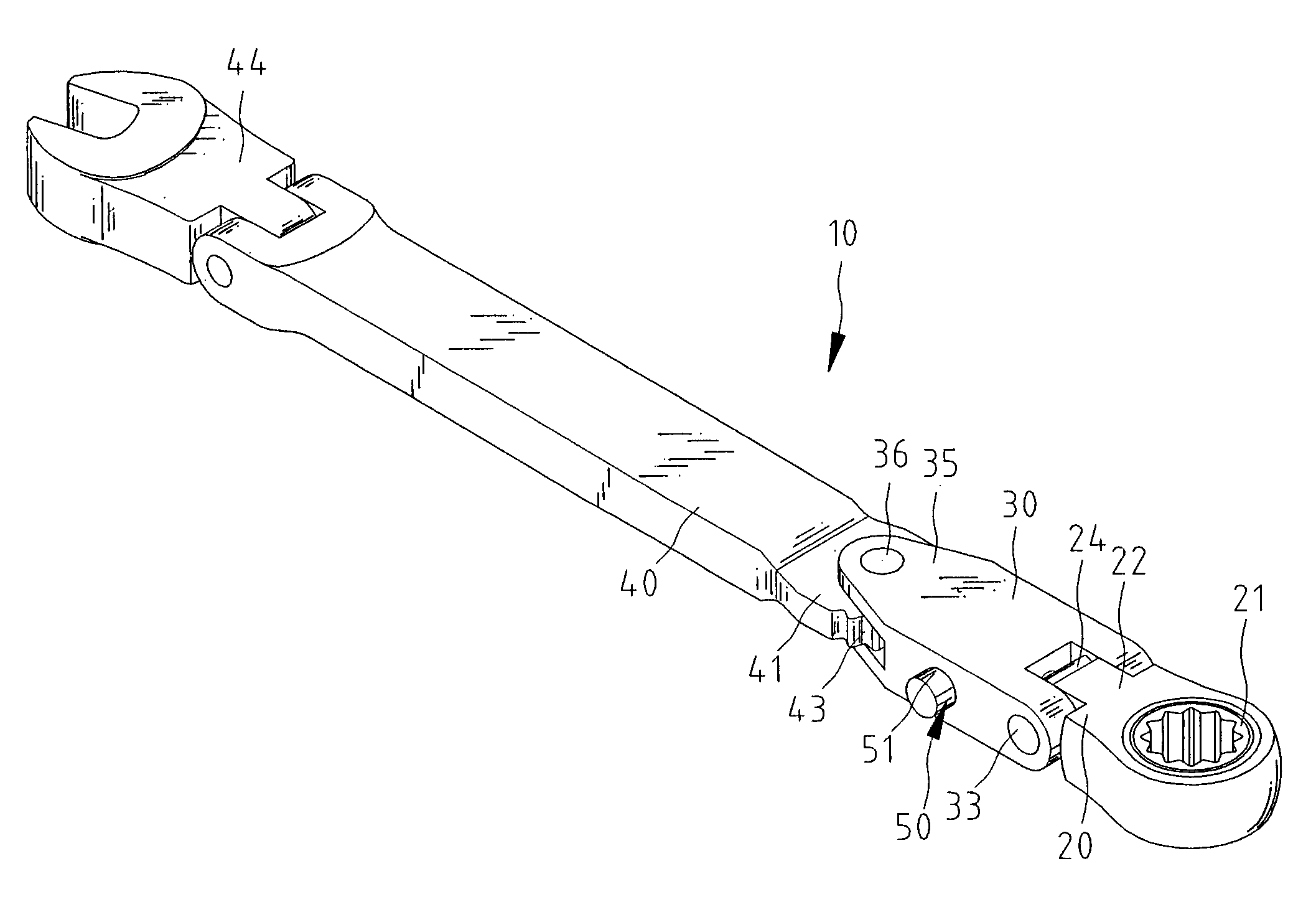
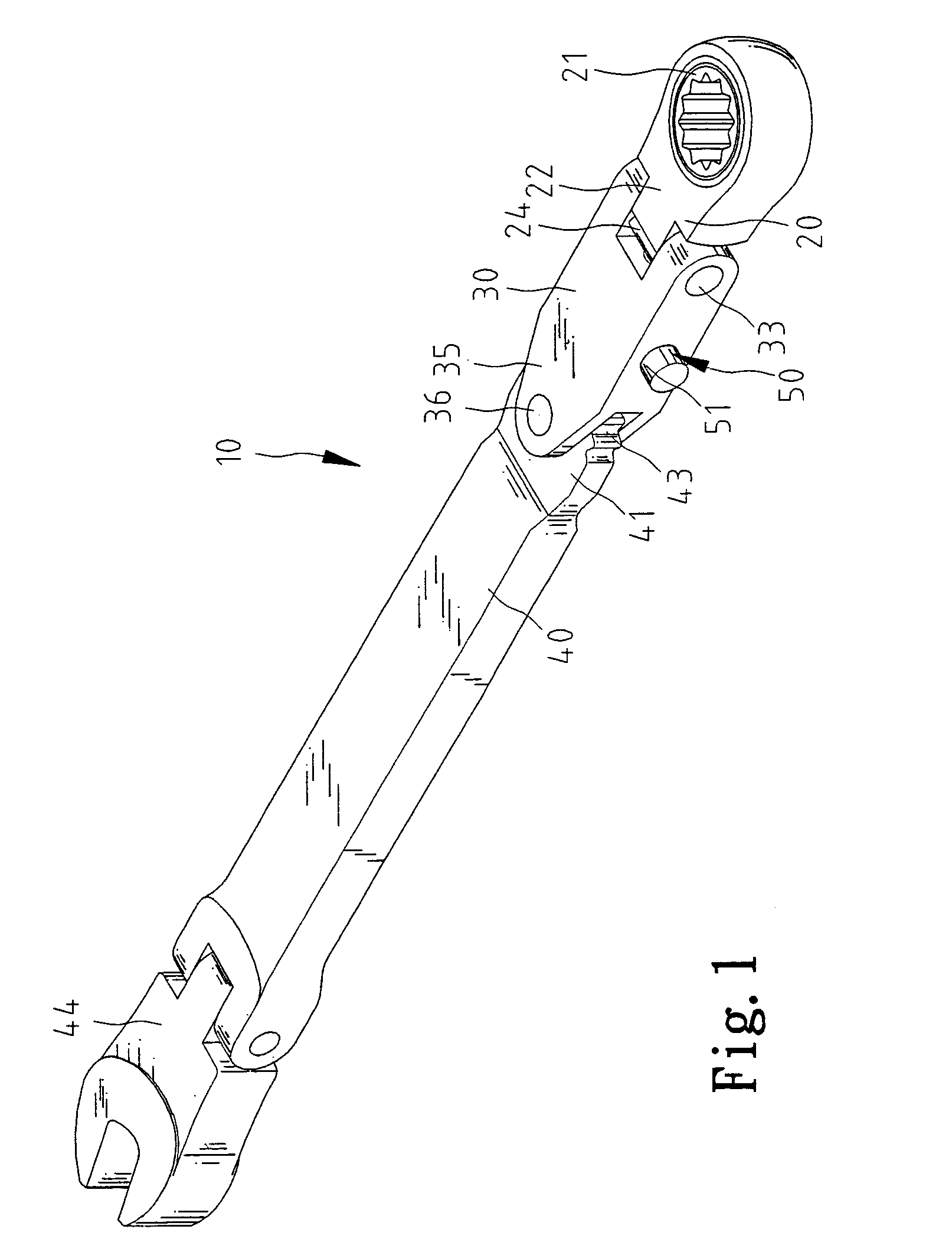
Referring to FIG. 1, according to the preferred embodiment of the present invention, a wrench 10 includes a head 20, a first handle 30 pivotally connected with the head 20 about a first axis and a second handle 40 pivotally connected with the first handle 30 about a second axis. The first and second axes are parallel to each other or not. A retaining device 50 can retain the first handle 30 in position relative to the head 20, and the second handle 40 in position relative to the first handle 30.

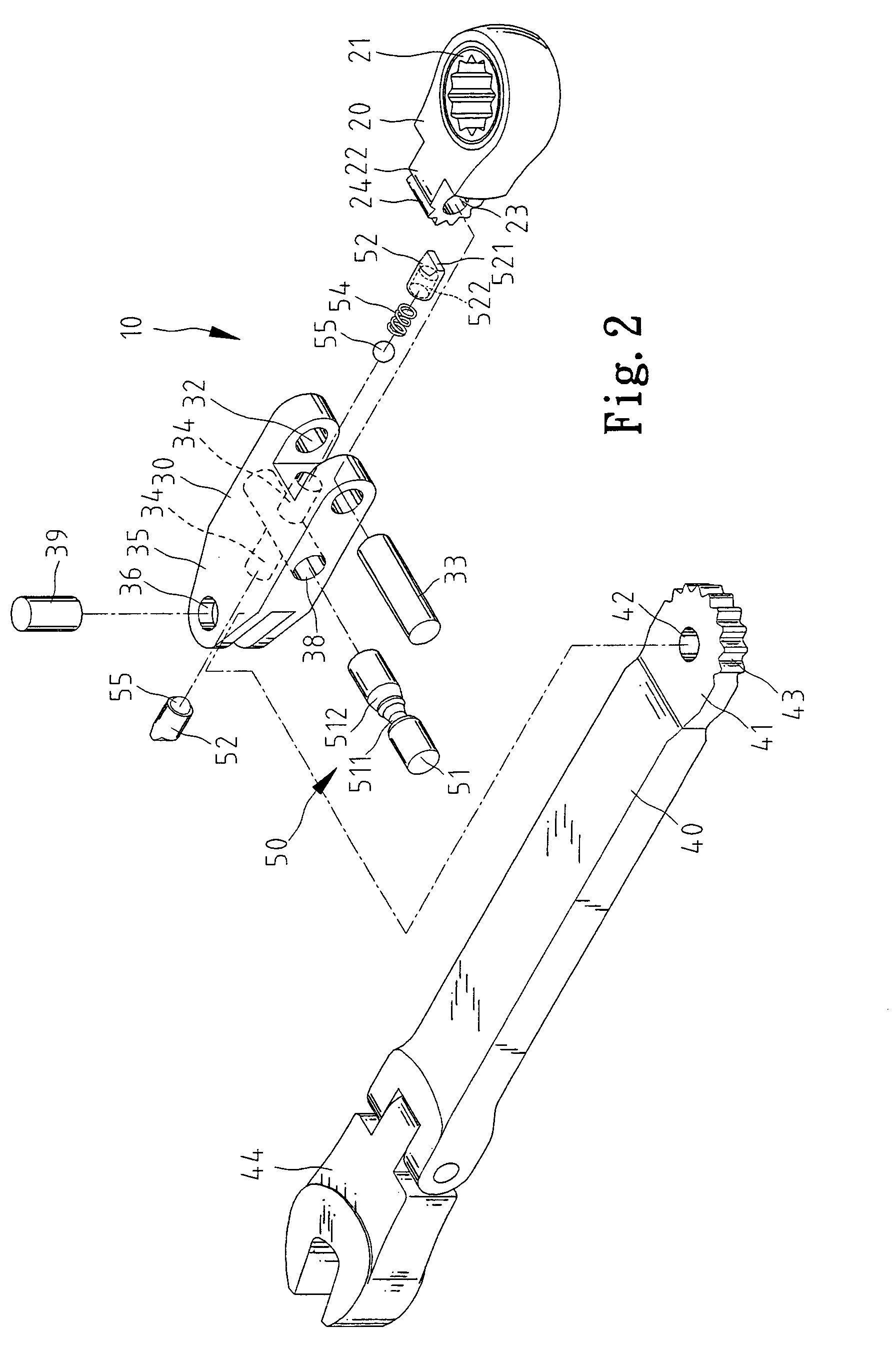
Referring to FIG. 2, the head 20 includes an annular portion in which an annular gear 21 is put. A mechanism (not shown) is arranged between the annular portion of the head 20 and the annular gear 21 so that the head 20 can drive the annular gear 21 in selective one of two directions.

The head 20 includes an ear 22 formed thereon. An aperture 23 is defined in the ear 22. The first handle 30 includes two ears 31 formed at a first end. An aperture 32 is defined in each of the ears 31. A pin 33 i...


PUM


Abstract

A wrench includes a head, a first handle, a second handle and a retaining device. The first includes first and second end. The first end of the first handle is pivotally connected with the head about a first axis. The second handle is pivotally connected with the second end of the first handle about a second axis. The retaining device can retain the first handle in position relative to the head, and the second handle in position relative to the first handle.

Description

FIELD OF INVENTIONThe present invention relates to a multi-joint wrench.BACKGROUND OF INVENTIONTaiwanese Patent Publication No. 135392 discloses a wrench including a head 10 and a handle 20. The head 10 includes an ear 11. The handle 20 includes two ears 21 between which the ear 11 is put. A bolt 24 is driven into a hole 23 defined in one of the ears 21, a hole 131 defined in the ear 11 and a hole 231 defined in the remaining one of the ears 21. Thus, the head 10 is pivotally connected with the handle 20, i.e., this conventional wrench can be bent. This conventional wrench can therefore be used in space that is limited and slightly bent; however, it cannot be operated in limited and crooked space.The present invention is therefore intended to obviate or at least alleviate the problems encountered in prior art.SUMMARY OF INVENTIONThe primary objective of the present invention is to provide a wrench including a configuration that can adapt to limited and crooked space.According to the...

Claims


Application Information

Patent Timeline
Patent Type & Authority Patents(United States)
IPC IPC(8): B25B13/00B25B13/46B25B23/00B25G1/00B25G1/06
CPCB25G1/063B25B13/461
Inventor CHEN, TERENCE
Owner CHEN TERENCE
Why Eureka
Try Eureka