Hinge cover integration into door seal edges

a technology of hinge cover and hinge mechanism, which is applied in the direction of hinges, wing accessories, transportation and packaging, etc., can solve the problems of dragging, turbulent flow and sealing problems of aircraft, limited space within fighter aircraft, and limit the choice of hinge mechanism, etc., and achieve the effect of superior sealing

Inactive Publication Date: 2005-04-12
THE BOEING CO
View PDF35 Cites 29 Cited by
  • Summary
  • Abstract
  • Description
  • Claims
  • Application Information

AI Technical Summary

Benefits of technology

In still another aspect of the present invention, the flexible hinge cover seal flexes from a relatively flat orientation when the door is closed into a bent configuration when the door is open. The bent configuration of the flexible seal, when the door is open, includes an ‘S’ shaped flap of material near each end of the flexible hinge cover seal and adjacent to the front & back door seal edges near the hinge. It is this ‘S’ shaped flap that allows for the integration of the ridged blade seals into the flexible hinge cover seal to provide a continuous seal around the door edge.
In yet another aspect of the present invention, a space efficient piano hinge is used in combination with a flexible hinge cover seal to seal an aircraft door. The arrangement provides superior sealing while using a minimum of payload space within the aircraft.

Problems solved by technology

Mold line gaps around in-flight operable doors create drag, turbulent flow and sealing problems for aircraft.
Compounding the problem there is limited space within a fighter aircraft for the door hinge mechanism.
This places a limit on the choice of hinge mechanism and some of the easier to seal hinge mechanisms require maximum space from the bays they are adjacent to.
This typically results in a complicated, bulky seal or a seal that does not cover the mold line gaps on the hinge side of the door.
However, the goose neck hinges require a substantially greater volume than a piano hinge because the hinge linkage are bulky.
This takes up valuable space in one or more bays of the aircraft.
This simplifies the seal because the hinge cover seal does not need to stretch, just bend, but again this results in a bulkier and more complicated hinge that takes more space from the bays adjacent to it.

Method used


Image

  • Hinge cover integration into door seal edges
  • Hinge cover integration into door seal edges
  • Hinge cover integration into door seal edges

Examples


Embodiment Construction

The following detailed description is of the best currently contemplated modes of carrying out the invention. The description is not to be taken in a limiting sense, but is made merely for the purpose of illustrating the general principles of the invention, since the scope of the invention is best defined by the appended claims.

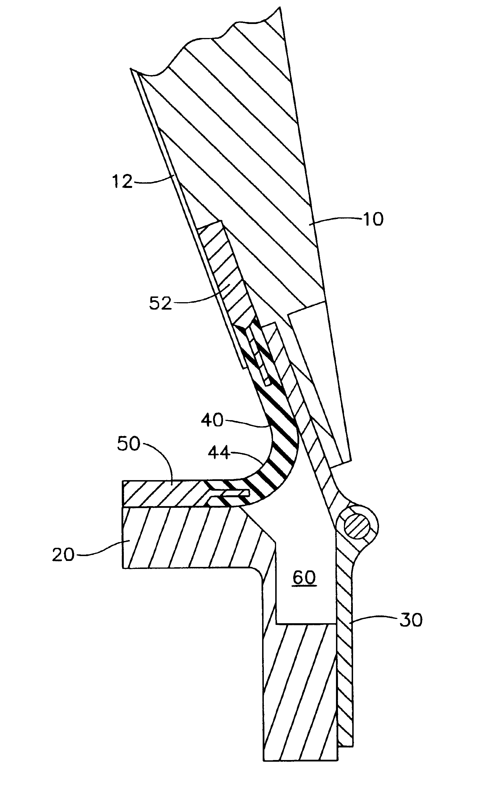
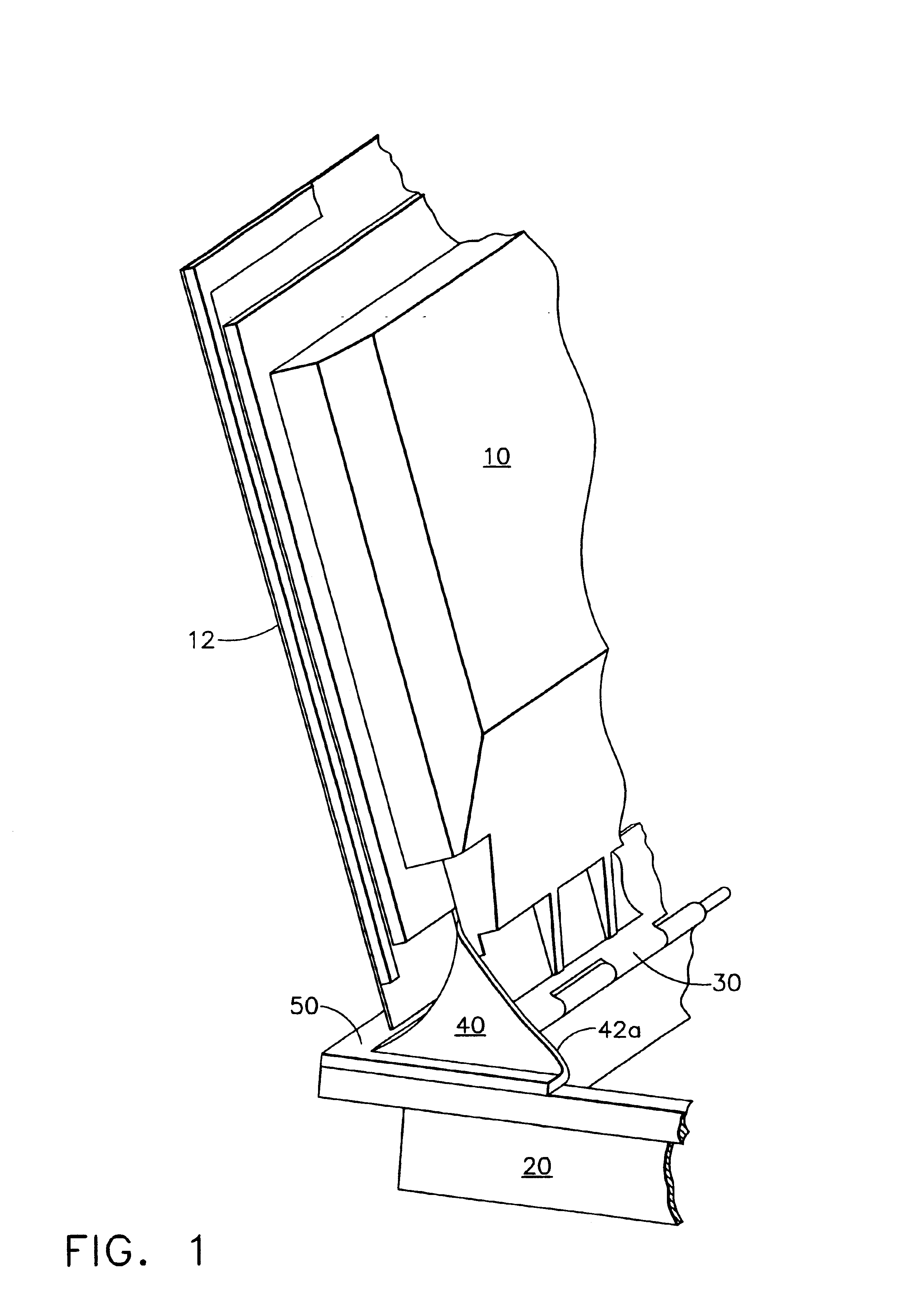
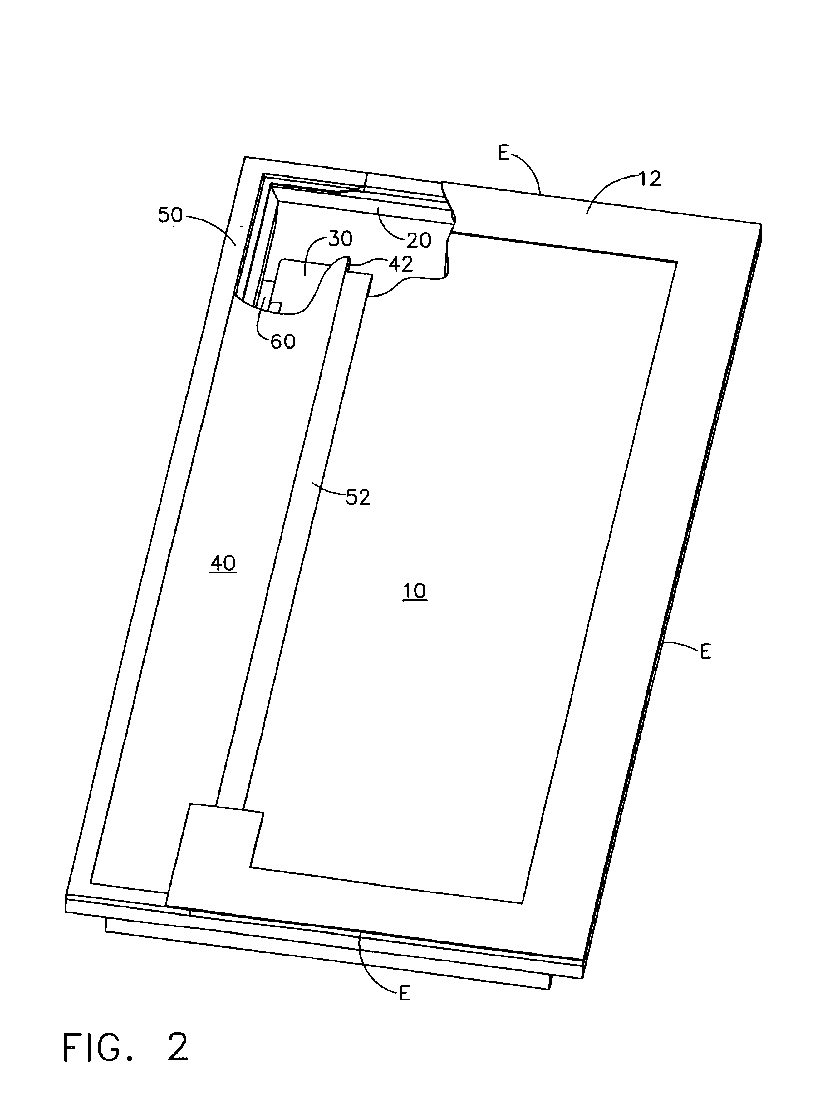
The present invention generally provides a flexible hinge cover seal that allows for the use of piano hinges with in-flight operable doors when aircraft volume is limited and elimination of aircraft surface gaps is paramount. Piano hinges collapse to a flat orientation that takes up almost no space when a door is closed. This space saving aspect of the piano hinge is very desirable in aircraft as space and payload are always at a premium. In addition to space savings, the piano hinge is simple having only one moving part. While these desirable aspects of piano hinges are well known, the use of piano hinges in the prior art has made it very difficult to seal a...


PUM

PropertyMeasurementUnit
flexibleaaaaaaaaaa
lengthaaaaaaaaaa
distanceaaaaaaaaaa

Abstract

An aircraft door includes a seal that integrates a flexible silicone seal portion and a rigid blade seal portion into a single continuous seal around the mold line gap between the door and frame. The arrangement allows for the use of space saving piano hinges to mount the door. The seal includes a rigid blade seal around three edges of the door and a flexible hinge cover seal adjacent to the hinge edge of the door. The flexible hinge cover seal is bonded to terminal blocks which in turn can be mounted to the door edge and to the door frame such that the flexible hinge cover seal covers the mold line gap adjacent to the hinge.

Description

BACKGROUND OF THE INVENTIONThe present invention generally relates to apparatus and methods for aircraft door seals and, more particularly, to apparatus and methods for aircraft door seals using piano type hinges.It is necessary to seal aircraft doors including those required in-flight operation such as weapons bay doors. Mold line gaps around in-flight operable doors create drag, turbulent flow and sealing problems for aircraft. Compounding the problem there is limited space within a fighter aircraft for the door hinge mechanism. This places a limit on the choice of hinge mechanism and some of the easier to seal hinge mechanisms require maximum space from the bays they are adjacent to. For example, a piano hinge mechanism is the simplest hinge that requires the least amount of space. But the piano hinge requires a hinge cover seal capable of adapting to a door hinge edge travel that requires a longer seal at door closure then when the door is open. As the piano hinged door closes, ...

Claims


Application Information

Patent Timeline
Patent Type & Authority Patents(United States)
IPC IPC(8): B64C1/00B64C1/14E05D11/00
CPCB64C1/14B64C1/1423E05D11/00E05D11/0054E05Y2800/12Y10T29/4987Y10T29/49885Y10T29/24Y10T29/4984Y10T29/49844E05Y2900/502
Inventor EVEKER, JAMES V.YOUNG, ROGER K.
Owner THE BOEING CO
Why Eureka
Try Eureka