Releaseable locking mechanism for rotatable boat seat

a technology of release mechanism and rotatable seat, which is applied in the direction of chairs, machine supports, crew accommodation, etc., can solve the problems of loss of resiliency and the loss of reliable locking arrangement, and achieve the effect of secure and positive locking arrangemen

Active Publication Date: 2005-04-12
GARELICK MFG
View PDF7 Cites 58 Cited by
  • Summary
  • Abstract
  • Description
  • Claims
  • Application Information

AI Technical Summary

Benefits of technology

The locking mechanism illustrated in the aforementioned '076 patent has an end of the extending lever arm contacting a resilient pad on the back or the outer side of the locking plate to hold the locking plate in place with its teeth engaging the slots or grooves or spaces between the teeth on the insert. A spring member is biased to move the locking plate away from engagement. To rotate the seat, the lever arm is moved so that it no longer impinges against the resilient pad on the locking plat

Problems solved by technology

Also, over a period of time a pad is likely to lose some of its resiliency so

Method used


Image

  • Releaseable locking mechanism for rotatable boat seat
  • Releaseable locking mechanism for rotatable boat seat
  • Releaseable locking mechanism for rotatable boat seat

Examples


Embodiment Construction

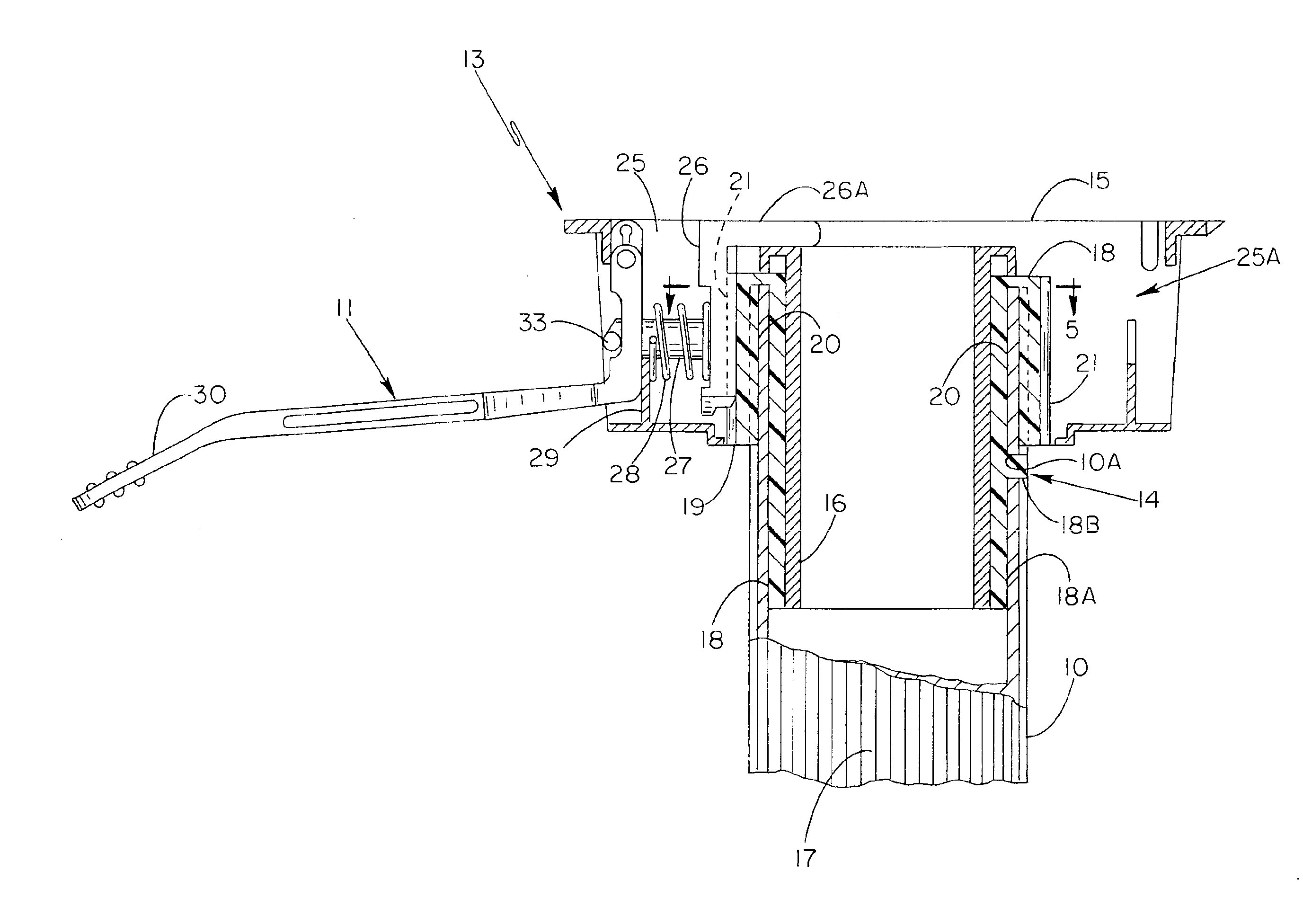
U.S. Pat. No. 5,884,887 tided “LOCK FOR SLIDE ADJUSTMENT OF BOAT SEAT OR TABLE TOP” describes an elevated slidably adjustable boat seat with a positive locking arrangement. The instant invention can be used in conjunction with the aforementioned invention so that the elevated boat seat is not only slidably adjustable and lockable fore and aft in the manner described in the '87 patent but also can be rotatably or swivably adjusted and positively releasably locked facing in the desired direction.

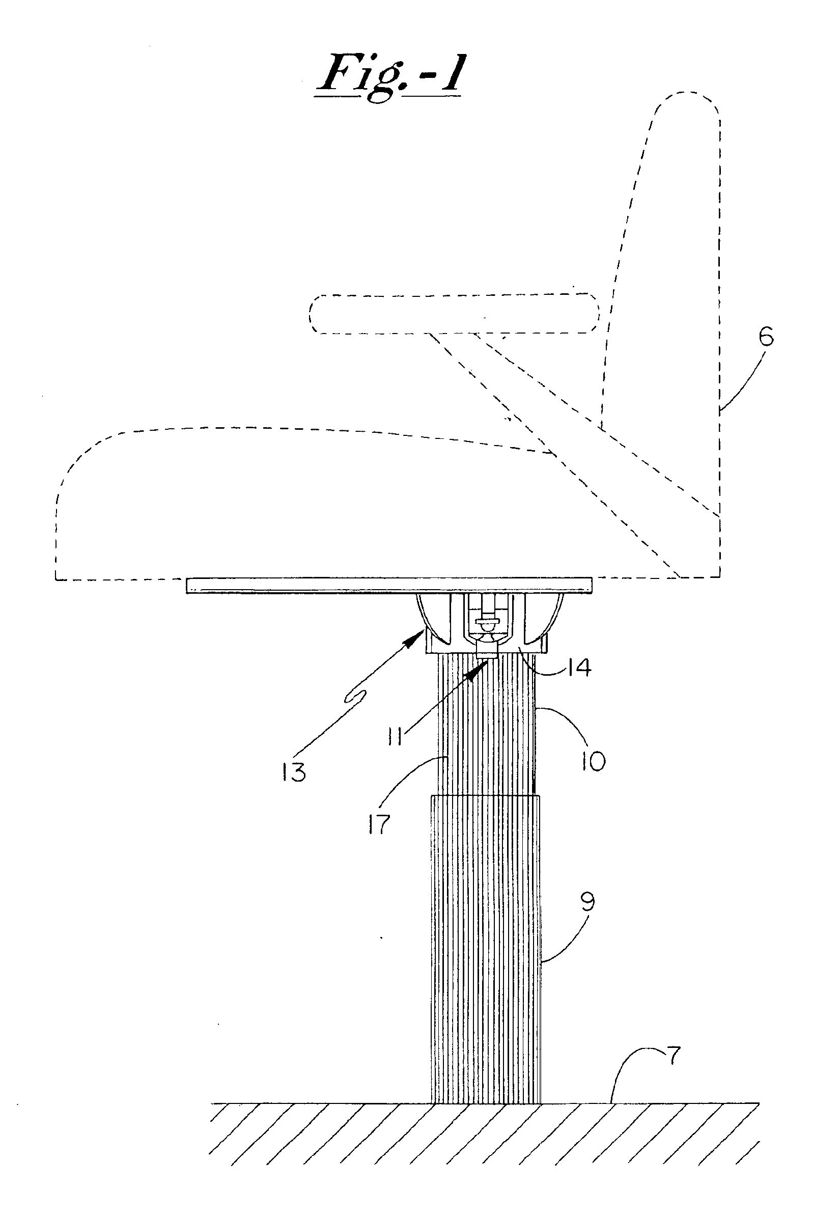
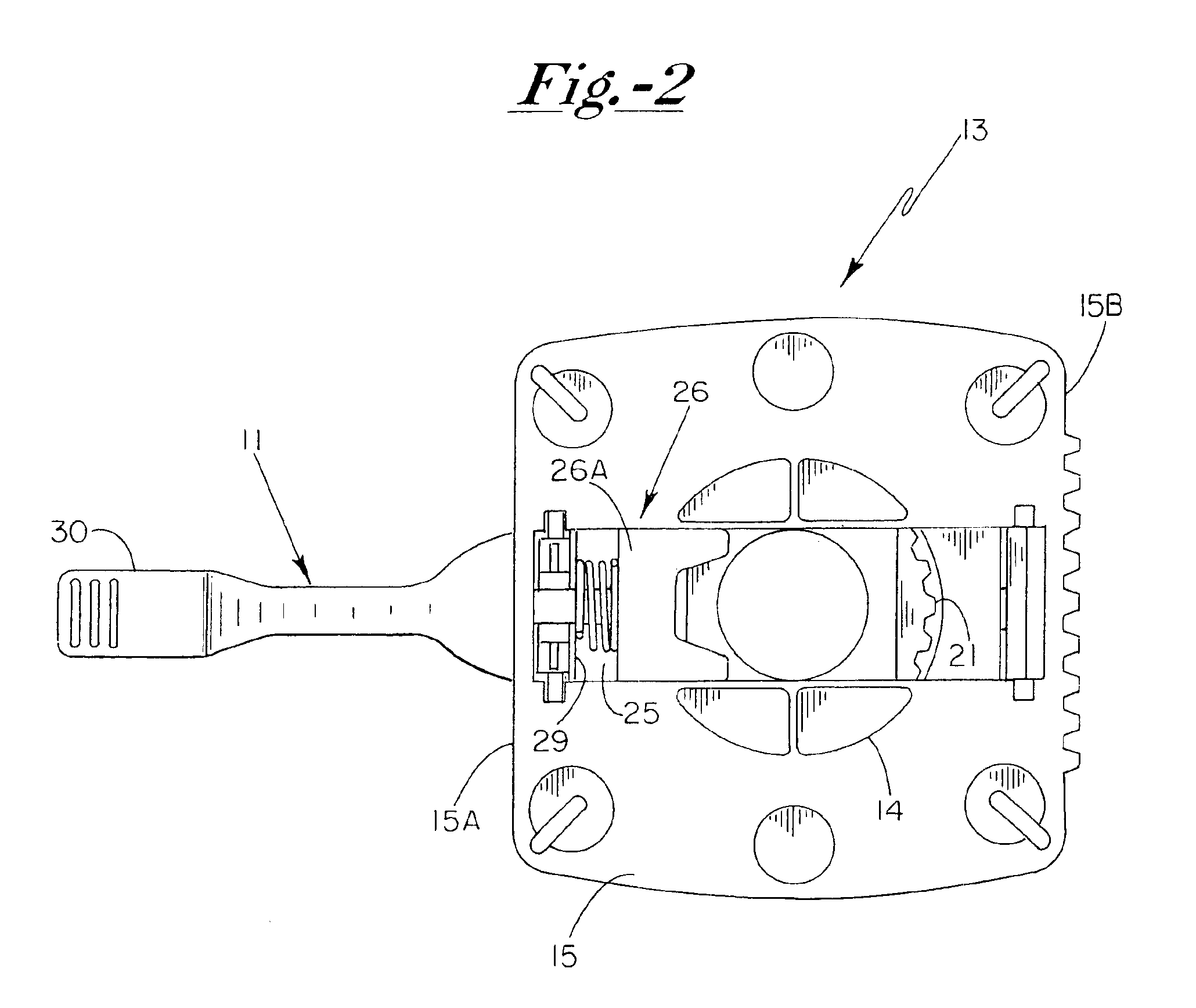
FIG. 1 illustrates a typical installation in which the instant invention is utilized. Conventionally and traditionally, a rigid circular hollow support post or column 10 extends vertically upward in a telescope arrangement from a tubular supporting pillar 9 which is attached at its base to the boat deck 7. Usually pillar 9 contains a suitable mechanism, not shown, for adjusting the height of column 10 to raise or lower the boat seat 6, shown in dashed line, which is attached at the top end. In...


PUM


Abstract

A boat seat is rotatably supported on a hollow, tubular, deck-mounted support post or column by a yoke or spider. A radially movable locking plate is biased by a spring member to rotatably lock the yoke in place and a lever arm can be operated to move the locking plate in opposition to the force of the spring member out of locking engagement to permit the seat to be rotatably adjusted.

Description

FIELD OF THE INVENTIONThis invention is aimed at adjustable boat seats which are mounted at the top of a pedestal or pillar or post which is anchored at the bottom to a suitable support usually the deck of the boat. More specifically, it is aimed at providing a mechanism for releasably locking a boat seat in place after it has been adjustably rotated or swung in a desired direction by the occupant of the boat seat.DESCRIPTION OF THE PRIOR ARTU.S. Pat. No. 5,882,076 dated Mar. 16, 1999 assigned to the same assignee as the instant application relates to the same function and purpose as the instant application and therefore appears to be the closest prior art that applicants are aware of. Other prior art which preceded the invention covered by the '076 patent is described in the aforementioned patent and the prior art description contained therein is incorporated herein by reference for the purpose of describing the known most pertinent prior art.SUMMARY OF THE INVENTIONTo some signifi...

Claims


Application Information

Patent Timeline
IPC IPC(8): A47C3/18A47C3/00B63B29/00B63B29/06
CPCB63B29/06A47C3/18
Inventor GARELICK, RICHARD J.
Owner GARELICK MFG
Why Eureka
Try Eureka