Sheet glass forming apparatus

a glass forming and glass sheet technology, applied in the field of glass sheet manufacturing, can solve the problems of limited apparatus, slow recovery from transient conditions, and subject to lower quality, and achieve the effect of reducing inhomogeneity in glass

Inactive Publication Date: 2005-06-30
CORNING INC
View PDF27 Cites 34 Cited by
  • Summary
  • Abstract
  • Description
  • Claims
  • Application Information

AI Technical Summary

Benefits of technology

[0025] In a preferred embodiment of the present invention, all the glass that forms the surface of the useful area of the sheet is virgin glass, which is not contaminated by flow in proximity to a refractory or refractory metal surface after the stirring operation. In addition, this embodiment significantly reduce inhomogeneities in the glass that forms the sheet by relocating or eliminating the regions of quiescent flow in the piping between the stirring device and the sheet glass forming apparatus.

Problems solved by technology

However, the apparatus has limitations.
A major drawback of the apparatus of “The Overflow Process” is that, even though it makes excellent glass over most of the surface, the surface of the glass sheet nearest the inlet is composed of glass that has flowed in proximity to the feeding pipe surfaces and therefore is subject to lower quality.
Another drawback of the apparatus of “The Overflow Process” is that, even though its makes excellent glass during stable operating conditions, it recovers from transient conditions very slowly.
During unintended process transient these quiescent zones slowly bleed glass of a previous material composition into the main process stream of glass causing defects.
These defects eventually subside when the process stabilizes; however, there is a period of time where the quality of the glass sheet is substandard.
Yet another drawback of the apparatus of “The Overflow Process” is the limited means for controlling the thickness of the formed sheet.
Another drawback of the apparatus of “The Overflow Process” is that the forming apparatus deforms during a manufacturing campaign in a manner such that the glass sheet no longer meets the thickness specification.
This is a primary cause for premature termination of the production run.
A further drawback of the apparatus of “The Overflow Process” is that surface tension and body forces have a major effect on the molten glass flow down the external sides of the forming apparatus causing the sheet to be narrower than the forming apparatus and the edges of the formed sheet to have thick beads.
These edge directors often extend below the bottom of the trough providing some influence to flow below the trough; however, the fixed shape, lack of adjustability and lack of a heating option limit their usefulness in minimizing and / or eliminating the bead at each edge of the sheet.
Another drawback of the prior art is that the glass sheet is not inherently flat when drawn from the forming apparatus.
Yet another drawback of the apparatus of “The Overflow Process” is that the drawing of the sheet from the bottom of the apparatus has a propensity to have a cyclic variation in sheet thickness.
As the apparatus ages, air leaks develop through cracks in material and assorted openings caused by differential expansion.
An additional drawback of the apparatus of “The Overflow Process” is that, even though it makes excellent glass during stable operating conditions, the control of process temperature and flow is limited by poor measurement technology, thus allowing unintended process transients which cause glass defects.
Defects caused by the flow and temperature transients eventually subside when the process stabilizes; however, there is a period of time where the quality of the glass sheet is substandard.
Another drawback of the apparatus of “The Overflow Process” is that the temperature of the glass in the forming apparatus is not measured.

Method used


Image

  • Sheet glass forming apparatus
  • Sheet glass forming apparatus
  • Sheet glass forming apparatus

Examples


Embodiment Construction

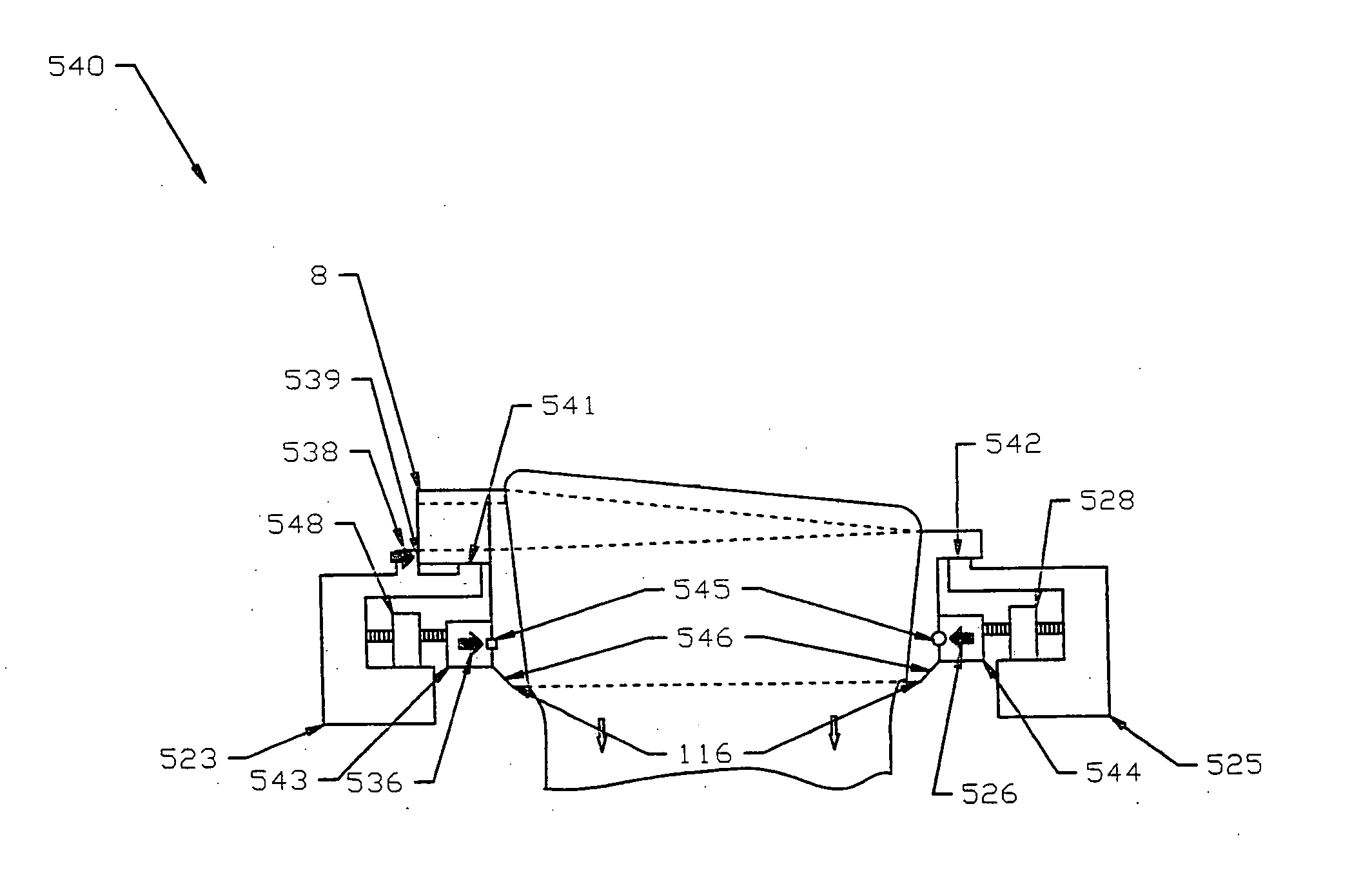
[0227] The flow dynamics of this invention are such that the outside surfaces of the glass sheet are formed from thoroughly mixed virgin glass that comes from the center of the glass stream flowing into the forming apparatus and thus has not contacted a refractory or refractory metal surface. This produces the highest possible surface quality. This pristine surface is essential for the manufacture of LCD / TFT semiconductor display devices. In addition, the flow dynamics in all embodiments of this invention are such that the flow rate of molten glass to the forming wedge at the bottom of the forming trough is substantially uniform over its width.

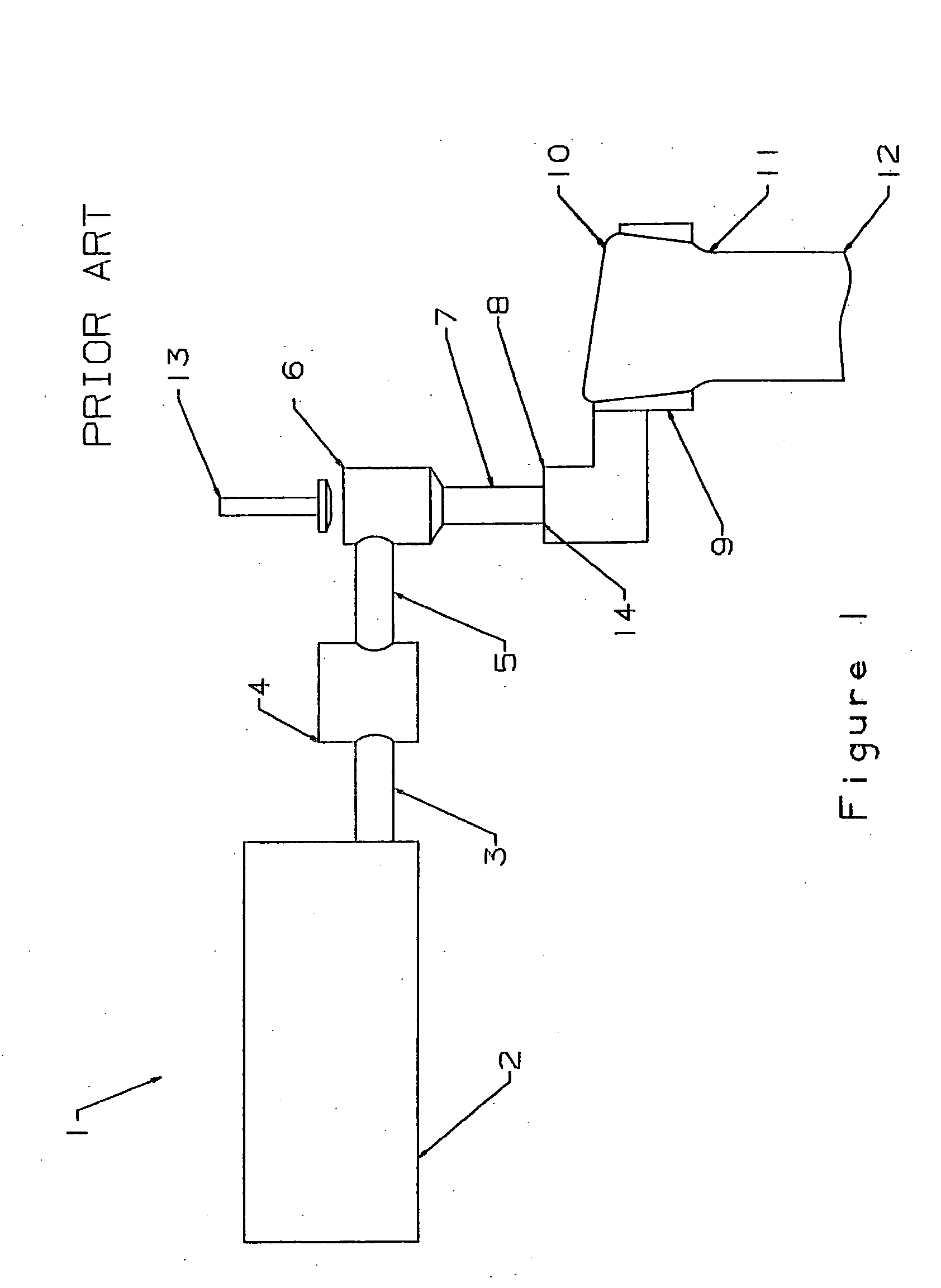
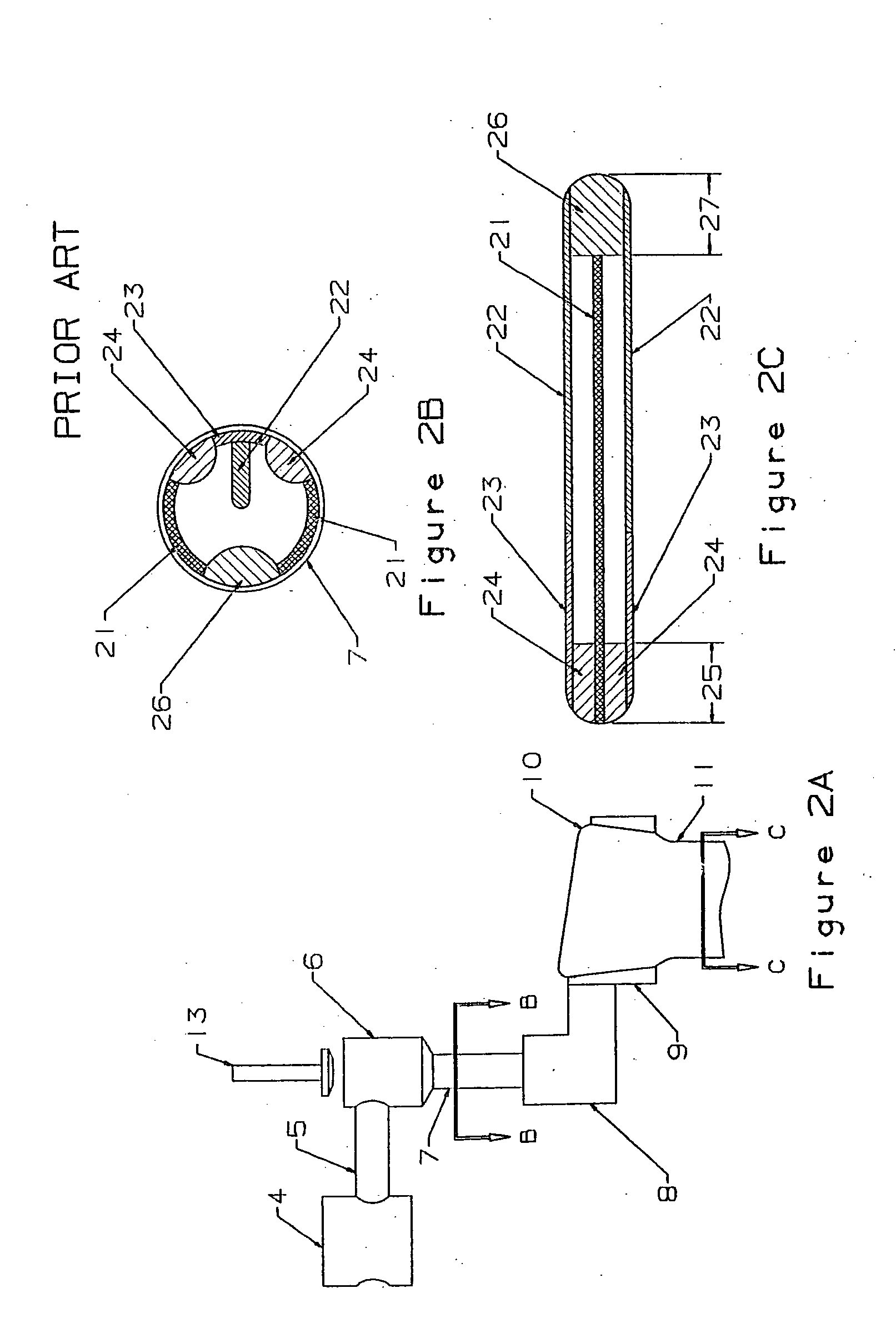
[0228] Referring to FIGS. 1, 11A and 11B, a typical “Overflow Process” manufacturing system (1) is shown. The glass (10) from the melting furnace (2) and forehearth (3), which must be of substantially uniform temperature and chemical composition, feeds a stirring device (4). The stirring device (4) thoroughly homogenizes the glass. The glass ...


PUM

PropertyMeasurementUnit
offset angleaaaaaaaaaa

Abstract

The present invention alters the flow path at the inlet of the sheet glass forming apparatus to improve quality. The bottom of the downcomer pipe is preferably shaped to alter the character of the vortex flow in the quiescent flow zone between the pipes. In another embodiment, a bead guide provides hydraulic stresses that are in opposition to the surface tension stress and thus reduces the influence of surface tension on the formation of thick beads on the edges of the sheet. The present invention also measures the temperature of the glass by immersing thermocouples in the glass, at locations where any defects caused by the immersion are in the glass that forms the unusable edges of the sheet. In another embodiment, the support structure for the trough is altered to substantially reduce the aging of the trough due to thermal creep.

Description

REFERENCE TO RELATED APPLICATIONS [0001] This application claims an invention that was disclosed in one of the following provisional applications: [0002] 1) Provisional Application No. 60 / 444,728, filed Feb. 4, 2003, entitled “SHEET GLASS FORMING APPARATUS”; [0003] 2) Provisional Application No. 60 / 449,671, filed Feb. 24, 2003, entitled “SHEET GLASS FORMING APPARATUS”; [0004] 3) Provisional Application No. 60 / 505,302, filed Sep. 23, 2003, entitled “TEMPERATURE MEASUREMENT FOR SHEET GLASS FORMING APPARATUS”; and [0005] 4) Provisional Application No. 60 / 534,950, filed Jan. 8, 2004, entitled “SHEET GLASS FORMING APPARATUS”. [0006] The benefit under 35 USC § 119(e) of the United States provisional applications is hereby claimed, and the aforementioned applications are hereby incorporated herein by reference. [0007] In addition, this application is a continuation in part of copending U.S. application Ser. No. 10 / 214,904, filed on Aug. 8, 2002, entitled “SHEET GLASS FORMING APPARATUS”. Th...

Claims


Application Information

Patent Timeline
Patent Type & Authority Applications(United States)
IPC IPC(8): C03B17/06
CPCC03B17/064C03B17/067
Inventor PITBLADDO, RICHARD B.
Owner CORNING INC
Why Eureka
Try Eureka