LED module

a technology of led modules and led modules, applied in semiconductor devices for light sources, planar light sources, lighting and heating apparatuses, etc., can solve the problems of increased light loss due to light blocking, unsatisfactory, complex structure of led modules, etc., and achieve the effect of improving the light emission efficiency of the first led device and bright ligh

Active Publication Date: 2015-11-05
CITIZEN WATCH CO LTD +1
View PDF8 Cites 35 Cited by
  • Summary
  • Abstract
  • Description
  • Claims
  • Application Information

AI Technical Summary

Benefits of technology

[0036]More specifically, there is provided an LED module comprising a first LED device whose side face is an optically transmissive face formed from a phosphor resin and a second LED device whose side face is a light blocking face formed from a white reflective member or the like, wherein the first LED device and the second LED device are arranged one adjacent to the other on a module substrate. Since this arrangement serves to prevent light emitted from the side of the first LED device from entering the second LED device, there occurs no shift in chromaticity, nor does light emitted from the second LED device enter the first LED device, and since the light emission efficiency of the first LED device improves, the LED module can produce bright light. Thus, according to the LED module, bright light can be produced without causing any shift in chromaticity even when the LED module is constructed by arranging tiny LED devices in close proximity to one another.

Problems solved by technology

One possible solution to this problem is to provide a light blocking wall to prevent light emitted from each LED device 200 from propagating in lateral directions, but this not only makes the structure of the LED module complex but increases the amount of light loss due to light blocking, which is not desirable.

Method used


Image

  • LED module
  • LED module
  • LED module

Examples


Embodiment Construction

[0052]Preferred embodiments of the present invention will be described in detail below with reference to the drawings. It will, however, be noted that the technical scope of the present invention is not limited by any particular embodiment described herein but extends to the inventions described in the appended claims and their equivalents. Further, throughout the drawings, the same or corresponding component elements are designated by the same reference numerals, and the description of such component elements, once given, will not be repeated thereafter. It will also be noted that the scale of the component elements is changed as necessary for illustrative purposes.

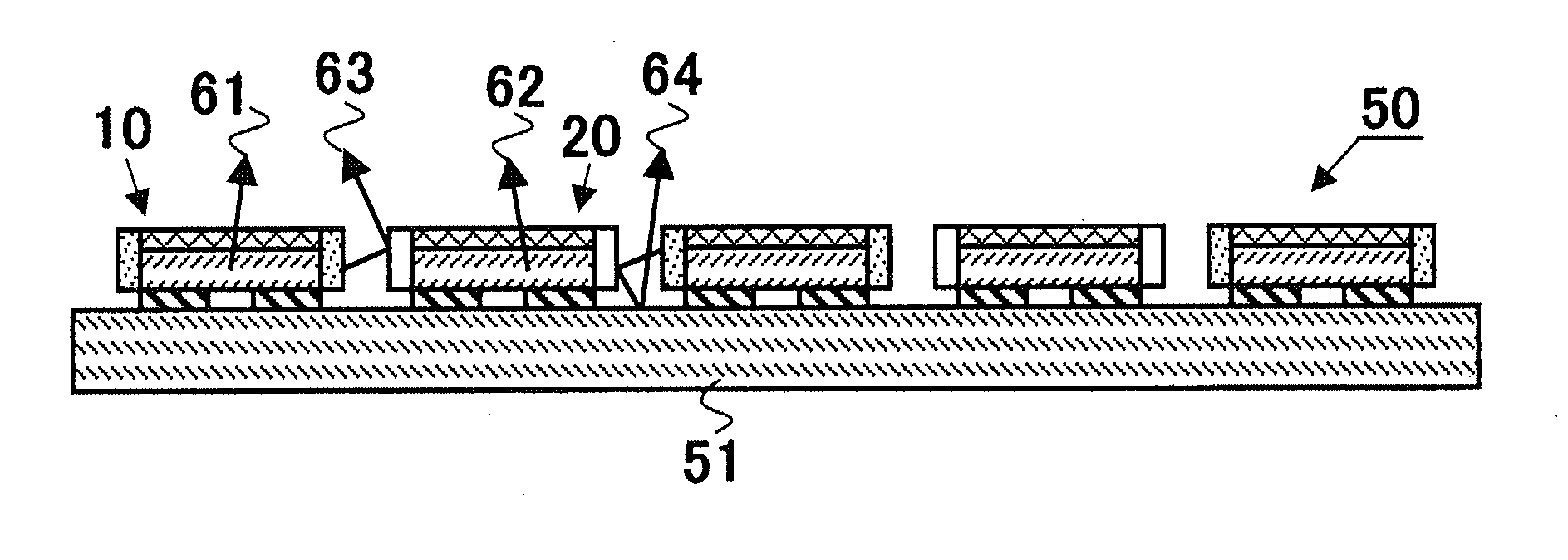
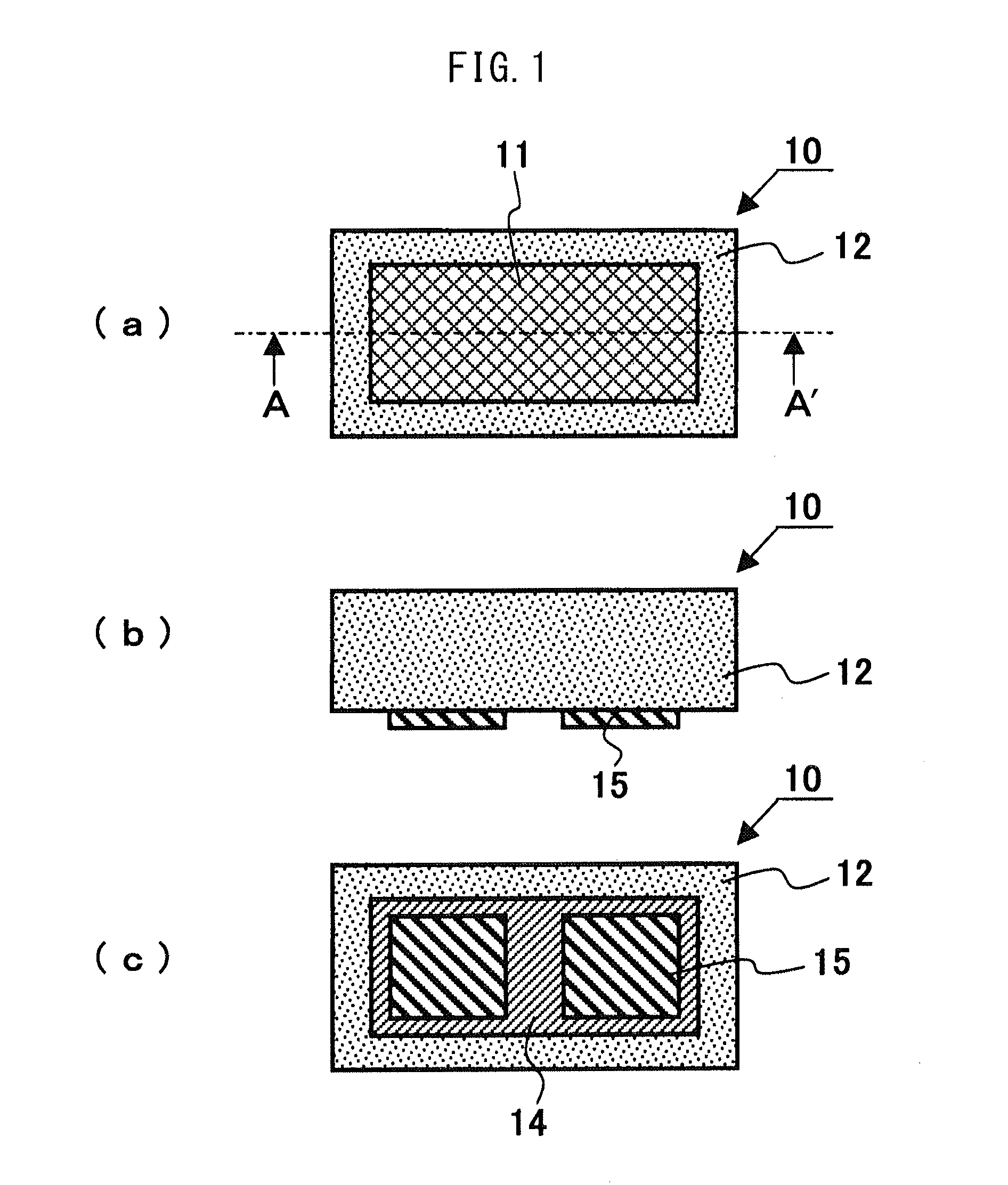
[0053]FIG. 1 shows the external appearance of an LED device 10 (first LED device) contained in an LED module 50 (see FIGS. 5 and 6); more specifically, FIG. 1(a) shows a top plan view, FIG. 1(b) shows a front view, and FIG. 1(c) shows a bottom view.

[0054]As shown in FIG. 1(a), when the LED device 10 is viewed from the to...


PUM


Abstract

Provided is an LED module which, even when CSP LED devices are arrayed adjacent to each other, emits light at a light emission color of a single LED device and is bright. An LED module includes a module substrate, first LED devices having a lateral surface which is configured of an optically transmissive face, and second LED devices having a lateral surface which is configured of a light blocking face. The first LED devices are mounted upon the module substrate adjacent to the second LED devices such that the translucent faces of the first LED devices and the light blocking faces of the second LED devices are in opposition.

Description

CROSS REFERENCE TO RELATED APPLICATIONS[0001]This is the U.S. National Phase application of PCT / JP2013 / 082231, filed Nov. 29, 2013, which claims priority to Japanese Patent Application No. 2012-264321, filed Dec. 3, 2012, the disclosures of each of these applications being incorporated herein by reference in their entireties for all purposes.FIELD OF THE INVENTION[0002]The present invention relates to an LED module in which LED devices, each in packaged form containing an LED die, are mounted on a module substrate.BACKGROUND OF THE INVENTION[0003]With an increasing demand for higher brightness, the size of LED dies as bare chips has also been increasing, and nowadays, LED dies measuring up to 1 mm by 0.5 to 1 mm in area size are commercially available. Since this area size is about the same as that of other chip components such as resistors, there has developed a need for an LED device constructed by packaging an LED die with a resin or the like to have about the same area size as t...

Claims


Application Information

Patent Timeline
Patent Type & Authority Applications(United States)
IPC IPC(8): F21K99/00H01L33/58H01L33/46H01L33/50F21V7/00H01L25/075
CPCF21K9/30F21V7/00F21K9/50H01L25/0753F21Y2105/003H01L33/505H01L33/58F21Y2103/003H01L33/46F21K9/20F21K9/60F21Y2103/10F21Y2105/10F21Y2105/12F21Y2115/10H01L33/56H01L2924/0002H01L2924/00
Inventor TOGAWA, MASATO
Owner CITIZEN WATCH CO LTD
Why Eureka
Try Eureka