Underwater Light Having A Faceted Water-Cooled Thermally Conductive Housing

a thermally conductive housing and underwater light technology, applied in the direction of light source semiconductor devices, lighting and heating devices, lighting support devices, etc., to achieve the effect of safe overdrive, bright light, and dissipation of concentrated hea

Active Publication Date: 2013-08-29
CARTRIDGE CORP OF AMERICA
View PDF3 Cites 3 Cited by
  • Summary
  • Abstract
  • Description
  • Claims
  • Application Information

AI Technical Summary

Benefits of technology

[0019]This novel invention also includes an improved transparent cover being one color and having a transparent lens being a different color. More particularly, the preferred combination is a colored lens to emit a dark colored light located in the center portion of the light projected through the water and a clear cover to emit a white light or lighter color to the outer perimeter of light projected through the water. This combination attracts marine life to the center dark color beam of light while the outer lighter color perimeter light allows spectators to view marine life more vividly. Though multi-color underwater lights aid in attracting and viewing marine life, they are also aesthetically pleasing to spectators. The transparent cover may have a lens that is permanently attached to the transparent cover. Additionally, the transparent cover may have a lens that is removable from the transparent cover. This removable feature is accomplished with the transparent lens having a transparent lens latching structure that is inserted into a transparent cover opening.
[0020]The improved water cooling system dissipates the concentrated heat associated with LEDs to a point external of an underwater light, resulting in a substantially brighter light without damaging the LEDs. By having a stable way of cooling LEDs with water, the LEDs can be safely overdriven, producing a brighter light than they were originally designed to produce.

Problems solved by technology

This is due to the constriction of the hardened resin around the surfaces of the sealing structure.

Method used


Image

  • Underwater Light Having A Faceted Water-Cooled Thermally Conductive Housing
  • Underwater Light Having A Faceted Water-Cooled Thermally Conductive Housing
  • Underwater Light Having A Faceted Water-Cooled Thermally Conductive Housing

Examples


Embodiment Construction

[0048]In the following detailed description of the preferred embodiments, reference is made to the accompanying drawings, which form a part hereof, and within which are shown by way of illustration specific embodiments by which the invention may be practiced. It is to be understood that other embodiments may be utilized and structural changes may be made without departing from the scope of the invention.

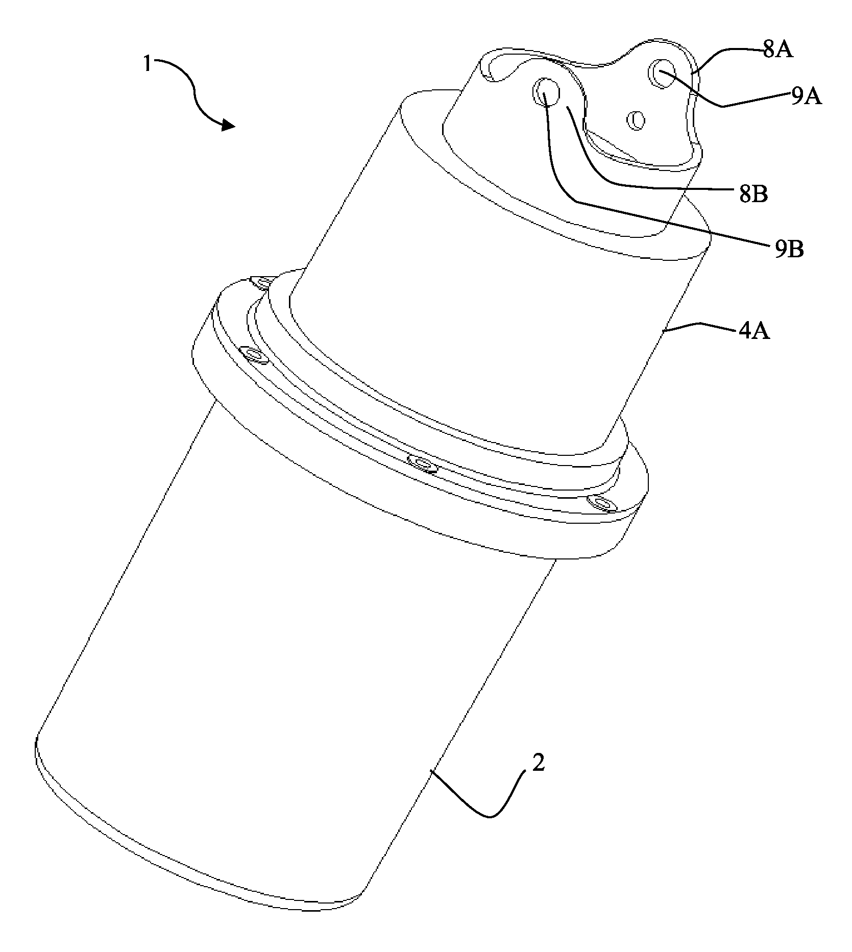
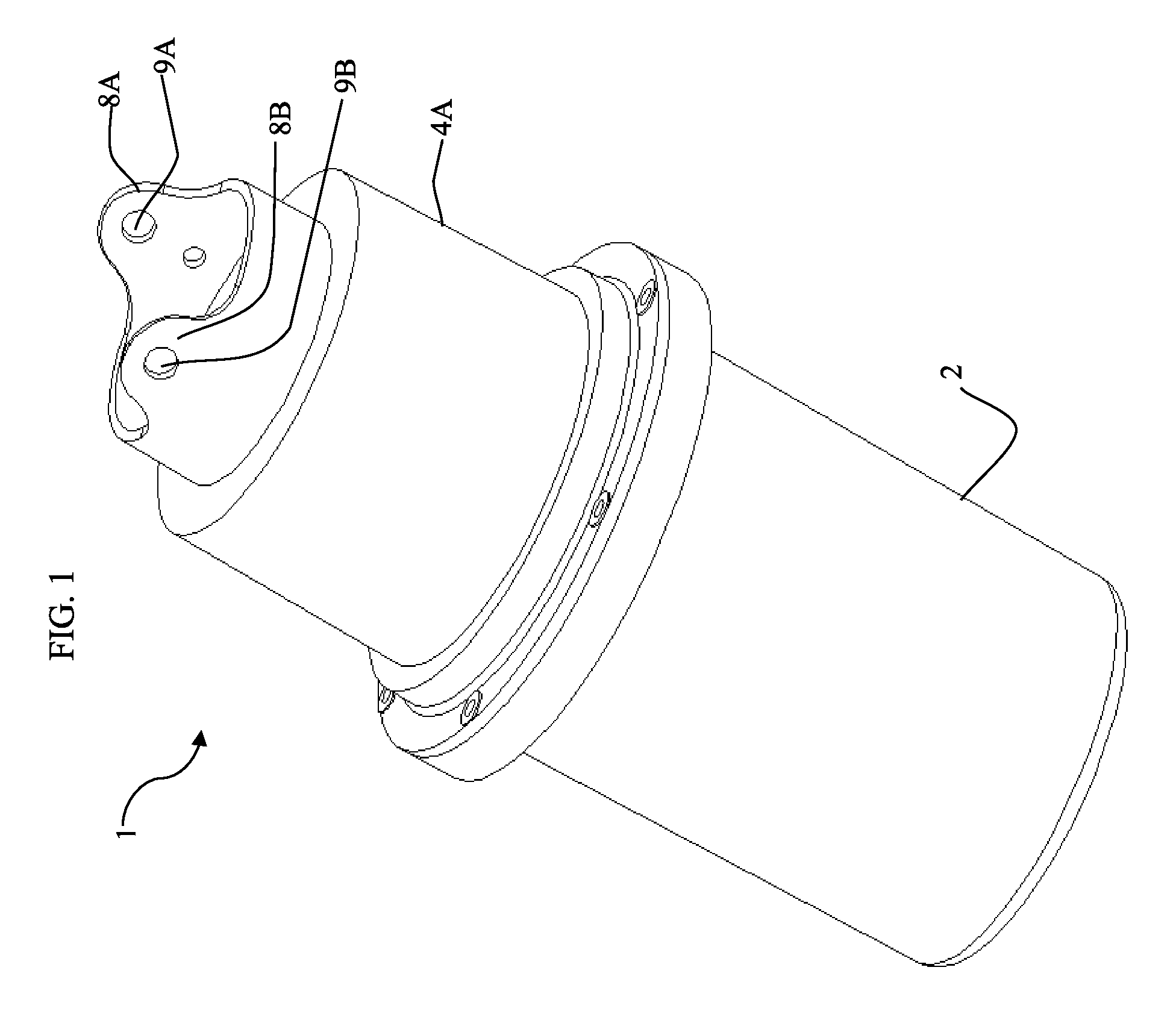
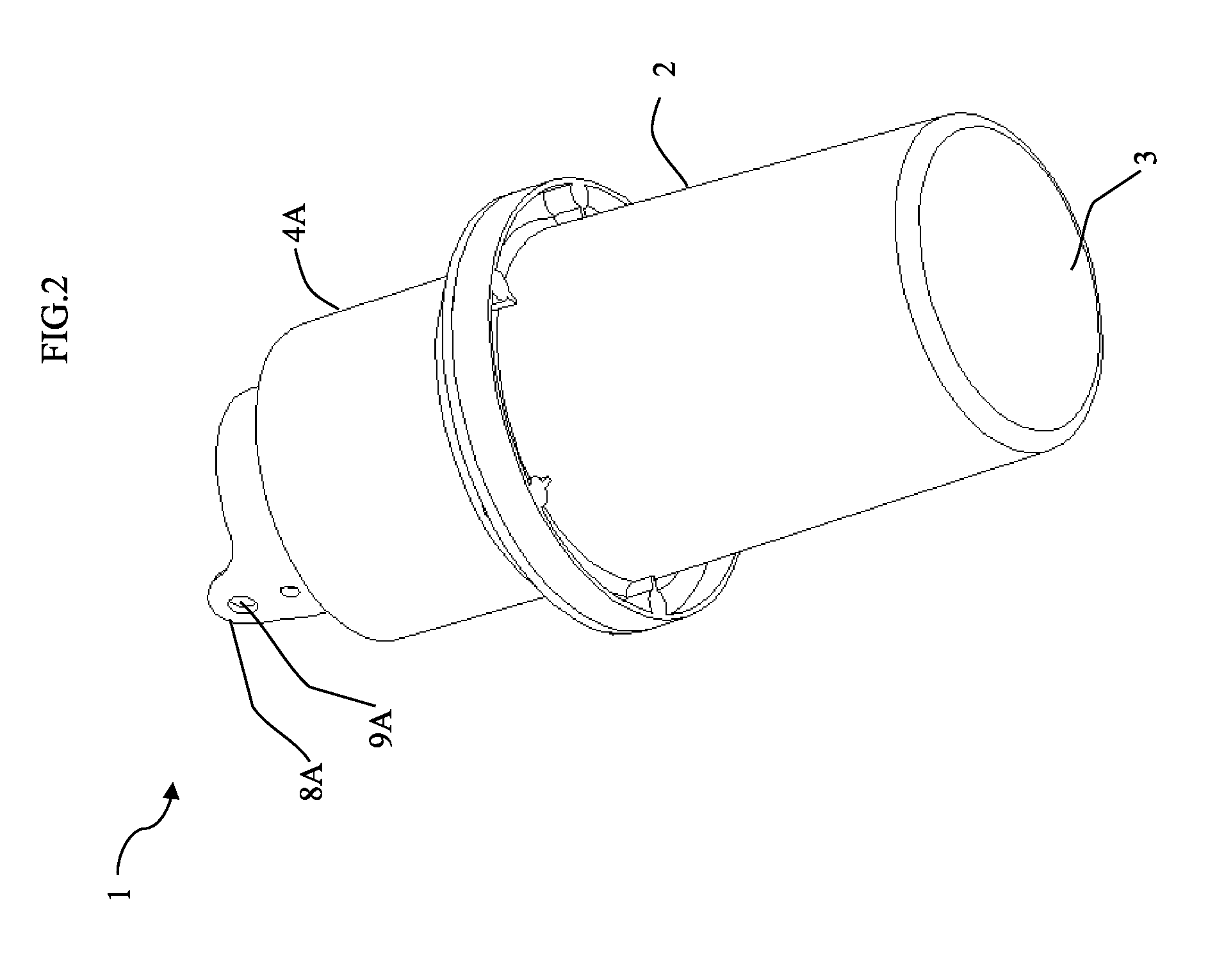
[0049]In a preferred embodiment, FIG. 1 shows the underwater light 1 has light fixture housing 4A located opposite transparent cover 2. Light fixture housing 4A has attaching structures 8A and 8B located on an end of the light fixture housing 4A. Attaching structures 8A and 8B are configured to equally suspend underwater light 1 in a body of water. Underwater light 1 displaces a volume of water, causing underwater light 1 to be buoyant. Attaching structures 8A and 8B each have attaching structure opening 9A and 9B to receive an attaching element (not shown). The attaching element inc...


PUM

PropertyMeasurementUnit
angleaaaaaaaaaa
angleaaaaaaaaaa
surface angleaaaaaaaaaa

Abstract

An ultra-high efficiency underwater light for attracting marine life having radially arranged facets supporting light emitting diodes (LEDs) that project a large perimeter of light underwater. A water cooling system allows the high powered LEDs to operate at sustained peak levels without sacrificing service life. A light bifurcating structure causes a central portion of water to illuminate in a different color than the color of the outer perimeter portion of water. A tire valve stem located on the underwater light is used to remove moisture bearing air and to also pressurize the light with a non-corrosive gas. Antifouling circuitry automatically cycles the underwater light on and off multiple times during periods of non-use. Smart circuitry communicates through a series of blinks and accepts commands from a user through a power cord.

Description

CROSS REFERENCE TO RELATED APPLICATIONS[0001]This application is a continuation application, entitled, “Underwater Light Having A Faceted Water-Cooled Thermally Conductive Housing,” which claims priority to U.S. Non-Provisional patent application Ser. No. 13 / 655,107 filed Oct. 18, 2012, entitled, “SYSTEMS AND METHODS FOR UNDERWATER LIGHTING.”BACKGROUND OF THE INVENTION[0002]1. Field of the Invention[0003]This invention relates, generally, to underwater dock lights.[0004]2. Background Art[0005]The light emitting unit in many conventional underwater lights are incandescent bulbs that are not energy efficient. Metal hydride lighting systems require the use of bulky transformers that are also not energy efficient compared to compact fluorescent lighting (CFL) or high intensity light emitting diode (LED) systems. Transformers make the assembly more costly and are unsightly. Incandescent, metal hydride, and CFL bulbs use hazardous high voltage A / C current. When these bulbs are used in und...

Claims


Application Information

Patent Timeline
Patent Type & Authority Applications(United States)
IPC IPC(8): F21V15/01F21V29/00
CPCF21V15/01F21V29/30F21V17/164F21Y2101/02Y10T29/49117F21V13/02F21V15/012F21V31/005F21V29/507F21Y2111/007F21Y2115/10F21Y2107/40F21V29/56
Inventor MILLER, STEVENMARQUES, ROBERT JOSEPH
Owner CARTRIDGE CORP OF AMERICA
Why Eureka
Try Eureka