Lighting assembly having a heat dissipating housing

a technology of light assembly and housing, which is applied in the direction of fixed installation, lighting and heating apparatus, lighting support devices, etc., can solve the problems of poor luminous efficiency, inconvenient use, and inconvenient use of lighting components, so as to achieve the effect of dissipating heat to an ambient atmospher

Inactive Publication Date: 2007-12-06
KORRUS INC
View PDF89 Cites 118 Cited by
  • Summary
  • Abstract
  • Description
  • Claims
  • Application Information

AI Technical Summary

Benefits of technology

[0010]Consistent with the present invention, there is provided a lighting assembly comprising a light module including a lighting element; an enclosure having a recess for receiving and housing the light module; a thermally conductive core connected to the light module through the enclosure; and a housing mounted in thermal contact with the core and the enclosure, so as to cause the housing to dissipate heat to an ambient atmosphere.

Problems solved by technology

However, it is often difficult to combine both form and function into a lighting assembly without compromising one or the other.
Incandescent bulbs, while inexpensive, are not energy efficient, and have a poor luminous efficiency.
Fluorescent bulbs require a ballast to regulate the flow of power through the bulb, and thus can be difficult to incorporate into a standard lighting assembly.
Moreover, LEDs generally fail by a gradual dimming over time, rather than abruptly burning out, as do incandescent bulbs.
LEDs, however, have heat-related limitations.
The performance of an LED often depends on the ambient temperature of the operating environment, such that operating an LED in an environment having a moderately high ambient temperature can result in overheating the LED, and premature failure of the LED.
Moreover, operation of an LED for extended period of time at an intensity sufficient to fully illuminate an area may also cause an LED to overheat and prematurely fail.
Active cooling mechanisms, such as fans, may be difficult to implement in a lighting assembly, as they often increase the size and power consumption of the assembly, and drain additional power.
Passive cooling structures, such as heat sinks, may also be difficult to incorporate as they increase the size of the lighting assembly.
Moreover, traditional heat sinks can be as much of a detriment to incorporation in traditional lighting assignments as a ballast can be in a fluorescent bulb assembly.

Method used


Image

  • Lighting assembly having a heat dissipating housing
  • Lighting assembly having a heat dissipating housing
  • Lighting assembly having a heat dissipating housing

Examples


Embodiment Construction

[0019]Reference will now be made in detail to the exemplary embodiments consistent with the present invention, an example of which is illustrated in the accompanying drawings. Wherever possible, the same reference numbers will be used throughout the drawings to refer to the same or like parts.

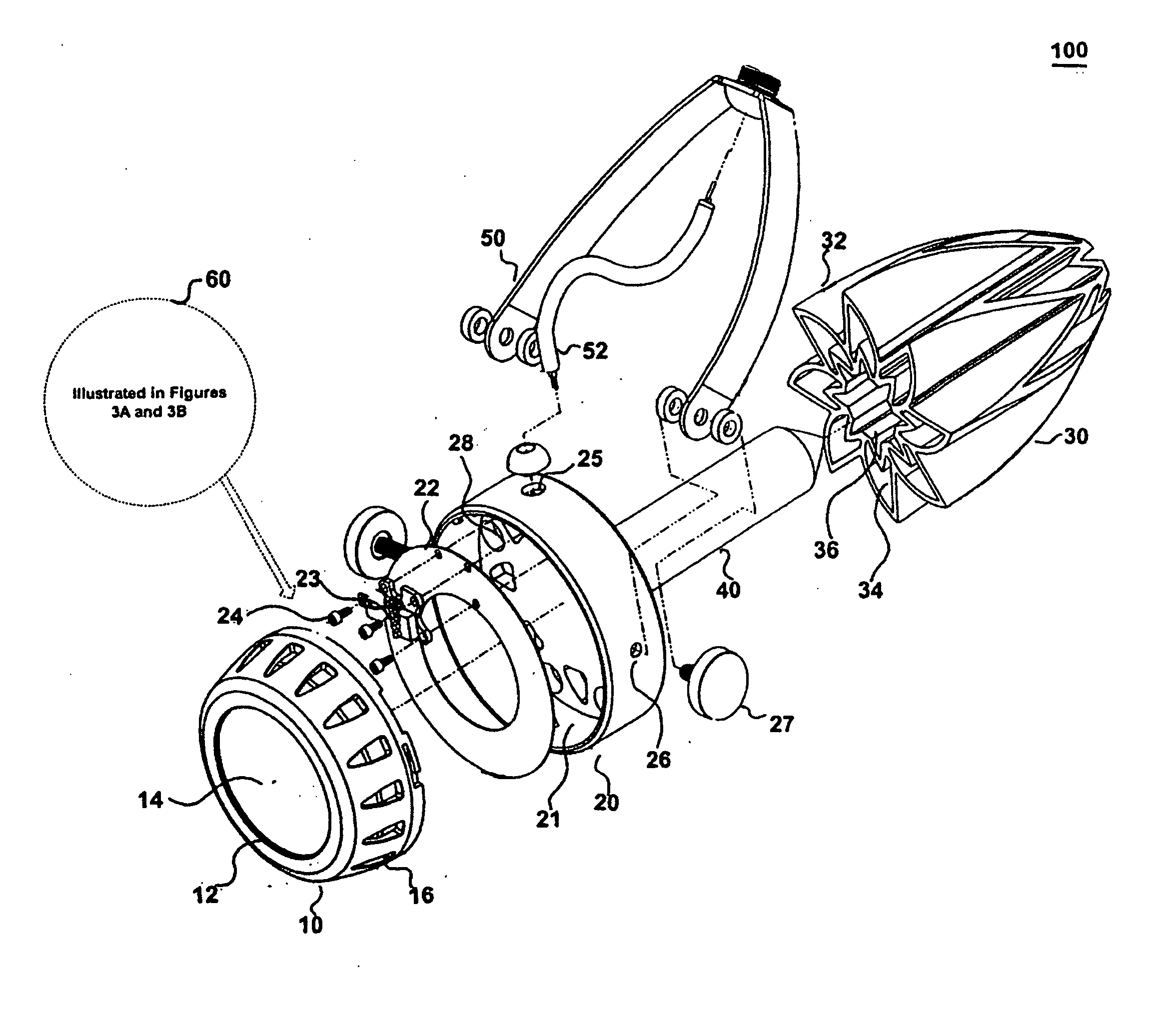
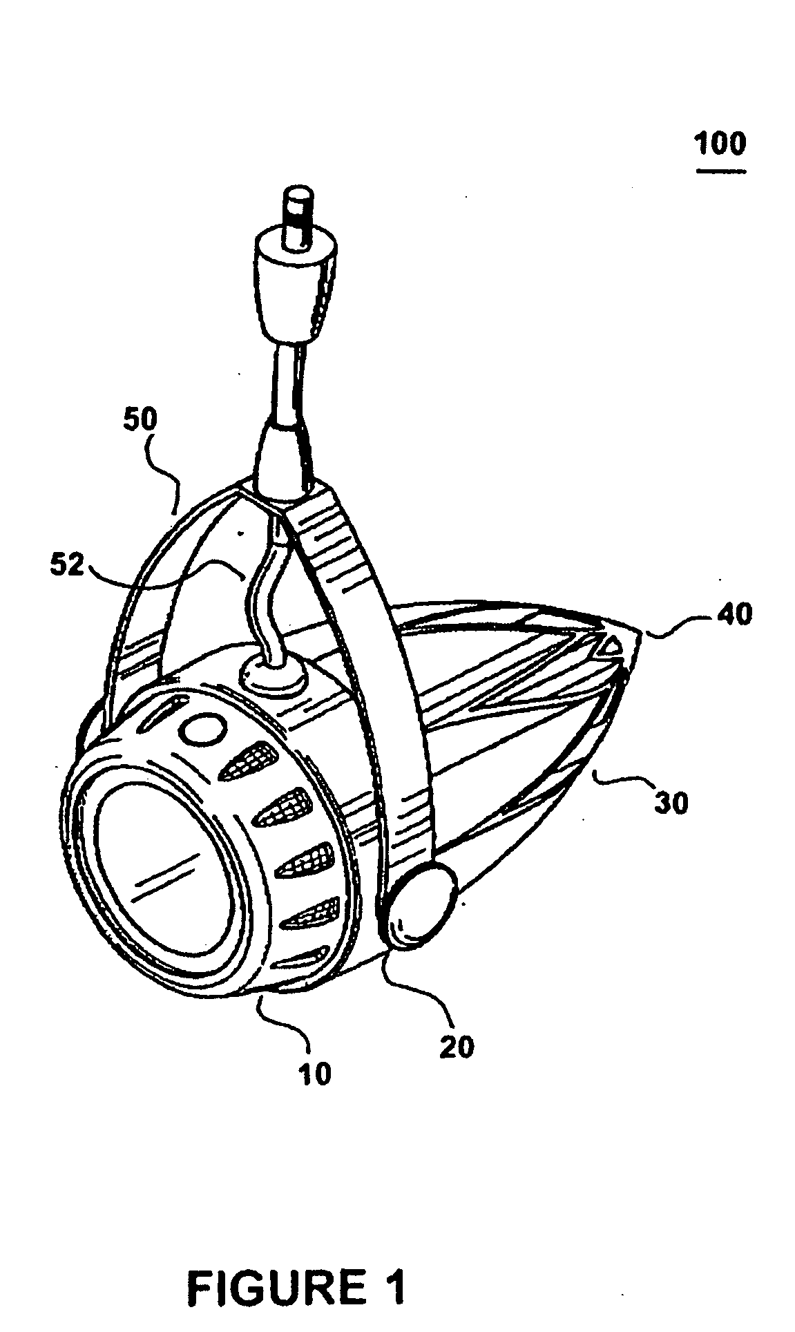
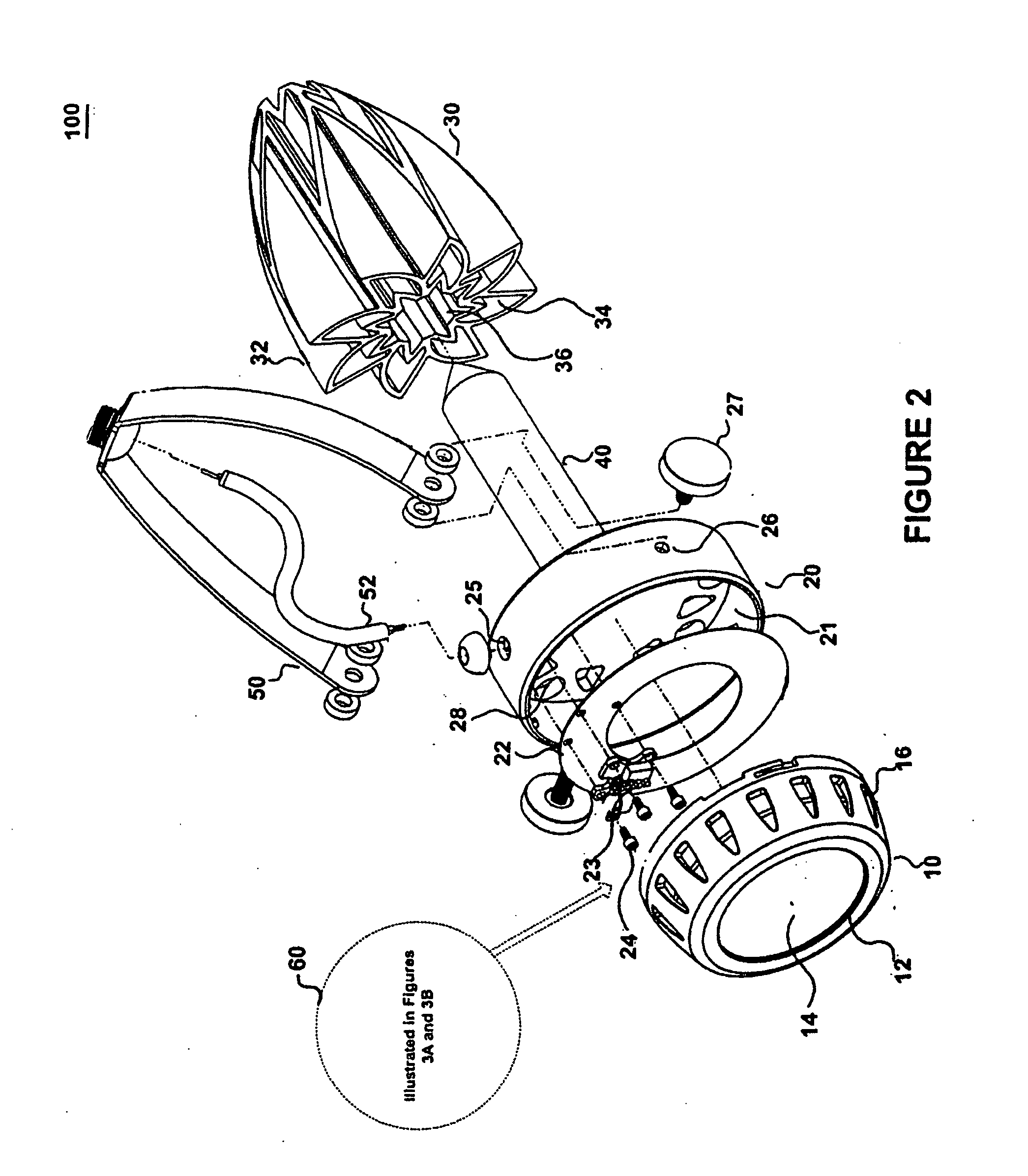
[0020]FIG. 1 is an illustration of a lighting assembly 100 consistent with the present invention. In one embodiment, lighting assembly 100 includes a protective cover 10, an enclosure 20, a housing 30, and a core 40. Further consistent with the present invention, lighting assembly may also include a light module 60, as illustrated in FIGS. 3A and 3B.

[0021]In some embodiments consistent with the present invention, lighting assembly may also include a mounting bracket 50, and a power cable 52. Mounting bracket 50 may be used to mount lighting assembly 100 to a stationary fixture, such as a wall, a light stand, or a ceiling. In an embodiment consistent with the present invention, mounting bracket ...


PUM

PropertyMeasurementUnit
thermally conductiveaaaaaaaaaa
transparentaaaaaaaaaa
forceaaaaaaaaaa

Abstract

A lighting assembly and a method for manufacturing a lighting assembly are provided. The lighting assembly includes a light module including a lighting element, and an enclosure having a recess for receiving and housing the light module. The lighting assembly also includes a thermally conductive core connected to the light module through the enclosure. The lighting assembly further includes a housing mounted in thermal contact with the core and the enclosure, so as to cause the housing to dissipate heat to an ambient atmosphere.

Description

PRIOR APPLICATION[0001]This application claims the benefit of priority to U.S. Provisional Patent Application No. ______, filed May 30, 2006, as Attorney Docket No. J / L103, entitled “Track Light,” the entire contents of which are hereby incorporated by reference in their entirety.BRIEF DESCRIPTION[0002]1. Technical Field[0003]The present invention is directed to a lighting assembly which may include passive cooling components integrated therein.[0004]2. Background[0005]Lighting assemblies such as lamps, ceiling lights, and track lights are important fixtures in any home or place of business. Such assemblies are used to not only illuminate an area, but often also to serve as a part of the décor of the area. However, it is often difficult to combine both form and function into a lighting assembly without compromising one or the other.[0006]Traditional lighting assemblies typically use incandescent bulbs. Incandescent bulbs, while inexpensive, are not energy efficient, and have a poor ...

Claims


Application Information

Patent Timeline
Patent Type & Authority Applications(United States)
IPC IPC(8): F21V29/00H05K13/04
CPCF21S8/038Y10T29/5313F21V15/01F21V15/013F21V15/04F21V19/045F21V21/30F21V29/004F21W2121/00F21W2131/30F21Y2101/02F21V29/006F21V19/0055F21V29/83F21V29/85F21S8/043F21Y2115/10F21V19/04F21V29/70
Inventor ALEXANDER, CLAYTONMETLEN, TODDBOTOS, DOUGMELROSE, JESSEWALKER, KEVIN
Owner KORRUS INC
Why Eureka
Try Eureka